

Global Positioning System
The Global Positioning System (GPS) is becoming an integral part of our daily lives. To maintain the compact and portable nature of GPS devices, designers frequently employ printed antennas. GPS applications operate within a narrow bandwidth of approximately 1.575 GHz to prevent interference. In this example, we demonstrate an HFWorks simulation for a patch microstrip antenna operating at 1.575 GHz with an exceptionally narrow bandwidth. The antenna's dimensions are approximately 2x2 cm, making it suitable for integration into portable devices.
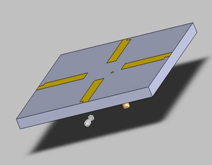
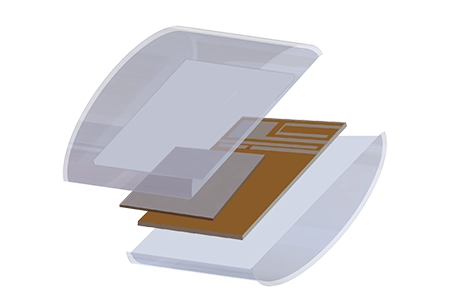
Figure 1 - GPS antenna 3D structure
The Perfect Electric Conductor (PEC) surfaces of the antenna are created using the Split Line feature.
Dimensions
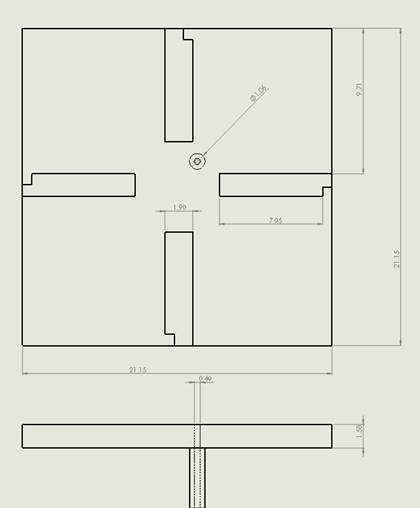
All dimensions are in millimeters (mm). The small size of the antenna makes it suitable for use in GPS applications for mobile devices.
Solids and Materials
Meshing
Results
With the meshing completed, we conducted an antenna simulation in the frequency range from 1.5 GHz to 1.65 GHz to precisely analyze the antenna's behavior around the intended frequency of 1.575 GHz for GPS applications. In the figure below, you can observe that the return loss increases rapidly from 0.3 dB to above 20 dB at the desired frequency, indicating a strong match for the GPS frequency.
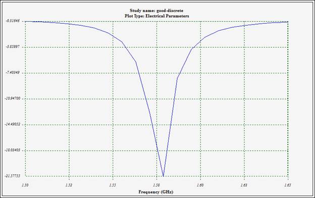
Figure 3 - Reflection coefficient at port 1
In the following figure, we have the radiation pattern of the total electric field, represented in both linear and dB scales, situated in the Phi=0 plane.
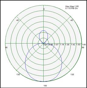
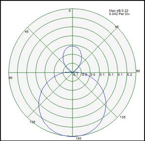
Figure 4 - Total radiated E field (in Linear and dB units) in Phi=0 plane
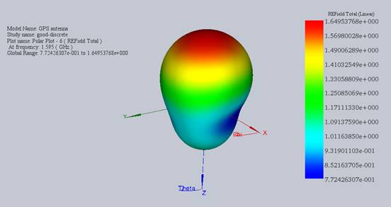
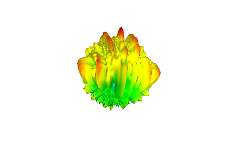
In this figure, we have plotted the 3D radiation of the electric field in a linear format.
Conclusion
This application note presents a concise exploration of designing a compact and efficient patch microstrip antenna for Global Positioning System (GPS) applications, operating at the precise frequency of 1.575 GHz. Utilizing HFWorks simulation, the study demonstrates the antenna's capability to function within the narrow bandwidth required for GPS signals, minimizing interference. The antenna, with its compact dimensions of approximately 2x2 cm, is ideal for integration into portable GPS devices. The simulation process involved careful consideration of materials, such as TMM 13 for the dielectric board and Duroid 5880 for the feed coax, and meticulous meshing to ensure accuracy, especially in critical signal paths. Results from the antenna simulation between 1.5 GHz and 1.65 GHz revealed an excellent return loss performance at the target frequency, showcasing the antenna's strong match for GPS applications. The detailed radiation pattern analysis further confirms the antenna's suitability for enhancing the functionality and reliability of GPS devices in our daily lives.

-(1).webp)