Wireless Power Transfer
Wireless power transmission technology is rapidly growing globally. In 2012, the market was under 1 billion, but by 2022, it's projected to exceed 5 billion. Consumer electronics dominate, with sectors like automotive and defense also expanding [2].
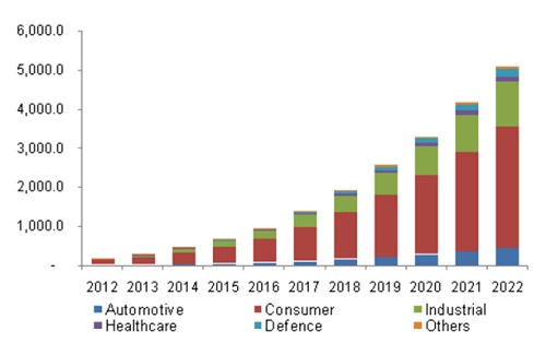
Figure 2 - Market trends for wireless power [2]
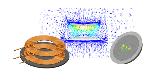
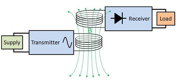
This article examines Inductive Power Transfer (IPT), a method of wireless power transfer. IPT utilizes a transmitter and receiver winding to form a transformer with an air gap. The transmitter, powered by a converter, generates high-frequency currents, inducing an EMF in the receiver winding through Faraday's law of induction. These currents are transferred to the load directly or through a power system.
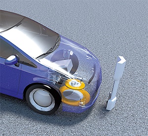
Given its reliability, efficiency, and speed, IPT finds applications in various fields, including electric vehicles. It enables wireless charging for electric cars, which can also wirelessly charge smartphones and laptops.
IPT technology, particularly in wearable and implanted medical devices (WIMD), revolutionizes healthcare by monitoring and regulating vital organs, thus extending and saving lives.
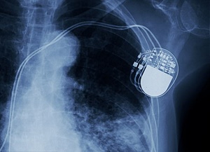
Pacemakers regulate irregular heartbeats like Arrhythmia with electrical impulses. Rechargeable and battery-less models, powered wirelessly or via RF systems, offer increased longevity and flexibility while reducing the need for surgeries.
Analysis of a WPT for pacemaker battery charging
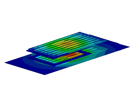
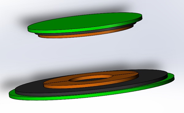
The proposed model [6] demonstrates inductive coupling for pacemaker battery recharging. Figure 5 illustrates the composed elements, including transmitter and receiver coils, aluminum plates, and ferrite cores. Operating at a low frequency (20kHz) ensures EMF standards compliance, although it reduces wireless power transfer efficiency. To mitigate this, aluminum plates and ferrite cores are incorporated to enhance system efficiency.
This article will analyze and compute the parameters of the wireless power transfer (WPT) system using EMS's AC Magnetic module coupled with an external circuit. Table 1 outlines the key simulation properties for reference.
Table 1: Main analysis properties
| Aluminum plates | Iron cores | Copper | Transmitter and Receiver Coil | |
| Electrical conductivity (S/m) | 3.86e+7 | 0 | 5.8e+7 | - |
| Relative permeability | 1 | 2400 | 0.99998 | - |
| Number of turns | - | - | - | 10 |
Pacemaker for WPT and Shielding effects
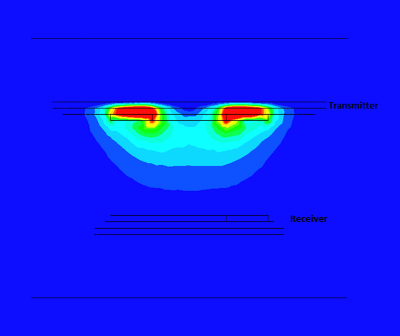
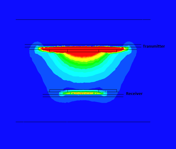
Figures 7-10 illustrate the magnetic flux density under various scenarios. Without shielding components, the flux density is symmetrical around the primary coil (Figure 7), with significant leakage into the air. Introducing aluminum plates reduces the field conducted to the receiver (Figure 8), while adding iron cores intensifies the field (Figure 9). In the full model, the magnetic flux is higher, following a direct path from transmitter to receiver (Figure 10). Shielding with iron cores and aluminum plates reduces losses and protects against leakage fields. Inductive coupling is approximately 0.1 without shielding and about 0.13 in the full model.
.png)
The WPT model's circuit parameters at a frequency of 20kHz are calculated using EMS. Table 2 provides a summary of these results.
Table 2: Results comparison of the studied WPT
| Inductance LTx (uH) | Inductance LRx (uH) | Resistance RTx ($$ \mathbf{m\Omega} $$) | Resistance RRx ($$ \boldsymbol{m\Omega} $$) | Mutual Inductance MTxRx (uH) | Coupling Coefficient | |
| EMS | 4.278 | 3.787 | 16.05 | 19.23 | 51.80 | 0.128 |
| Ref [3] | 4.1685 | 3.7002 | 18.78 | 21.89 | 52.26 | 0.133 |
Influence of the air gap distance on the coupling coefficient
The coupling coefficient formula for the WPT system is:$$ k = \frac{M}{\sqrt{L_T \times L_R}} $$ .. The efficiency of WPT increases with the coupling coefficient. Perfect coupling (k = 1) occurs when all flux lines of one coil cut all turns of the second coil, resulting in mutual inductance equal to the geometric mean of the two individual inductances. This leads to induced voltages satisfying the relation$$ \frac{V_1}{V_2} = \frac{N_1}{N_2} $$.
Figure 11 presents an animated visualization showcasing the magnetic flux density's response to changes in the air gap distance between the transmitter and receiver coils. A parametric AC Magnetic study vividly demonstrates the inverse relationship: as the air gap distance increases, the magnetic flux density reaching the secondary coil diminishes, and vice versa.
Figures 12 and 13 display the curves depicting the mutual inductance and coupling coefficient concerning the air gap between the primary and secondary coils. In both cases, as the air gap distance increases, both parameters exhibit a decrease, indicating a weakening coupling between the coils.
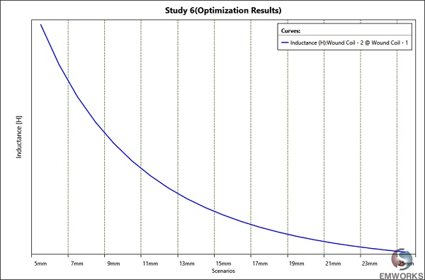
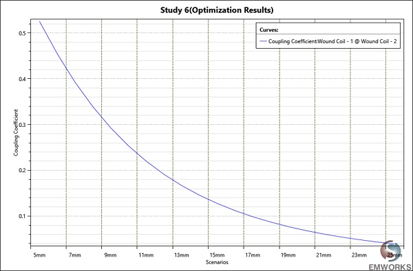
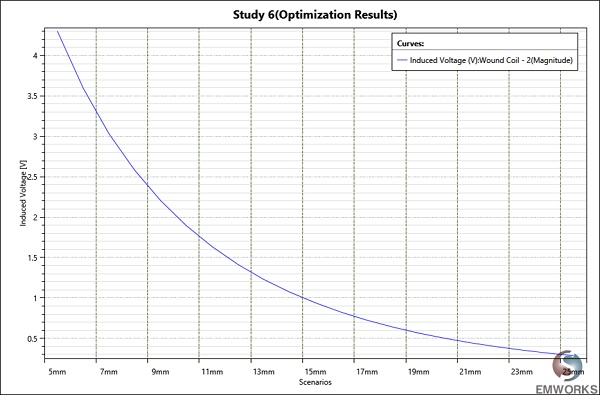
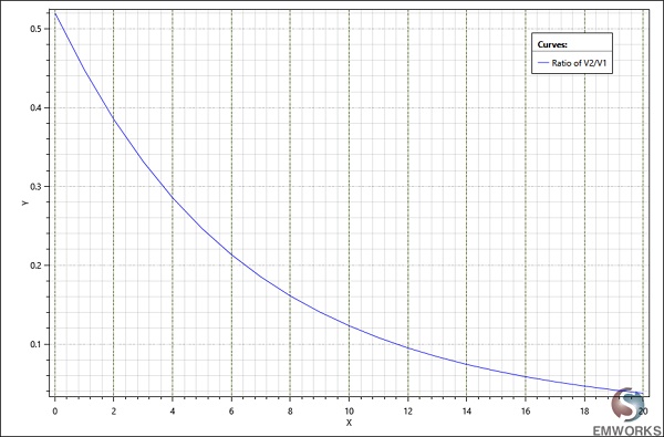
Figure 14 illustrates the induced voltage in the secondary coil, mirroring the behavior of the coupling coefficient. Meanwhile, Figure 15 depicts the ratio of $$ \frac{V_2}{V_1} $$ . , which decreases as the air gap widens. This decrease signifies a reduction in transferred energy due to increased distance between primary and secondary windings, aligning with previous observations.
WPT operating at the resonance
The WPT system achieves its peak efficiency when operating at resonance, facilitated by the addition of resonant capacitances on both primary and secondary sides. The external circuit, integrated within EMS, is depicted below. In this circuit representation, the source is ideal (R=0), while the DC resistance of the windings is internally accounted for within EMS and not explicitly modeled.
The resonant capacitance values are computed using the following formula : $$ \omega_r = \frac{1}{\sqrt{LC}} $$
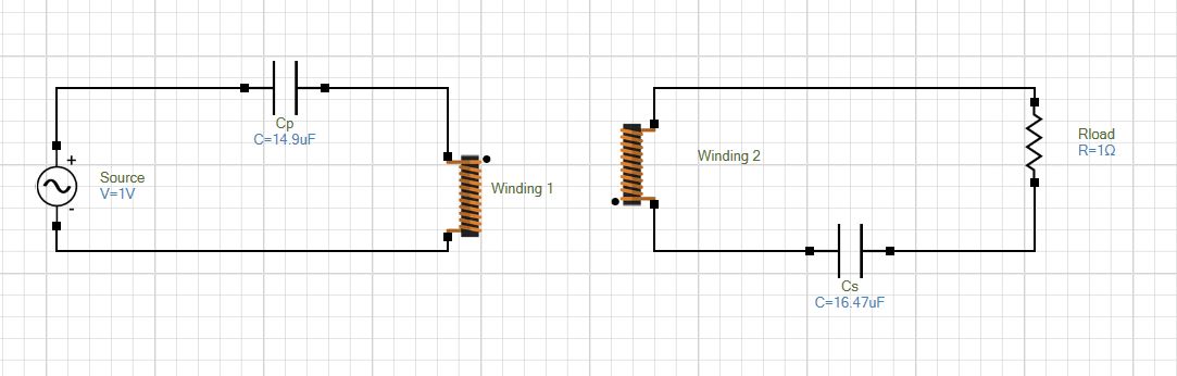
Figure 17 illustrates the variation of both transmitter and receiver currents across different operating frequencies. It's evident that the maximum current is achieved at the resonant frequency of 20kHz.
WPT system inside human body
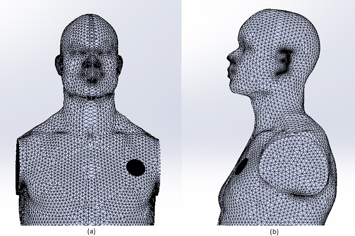
In this section, we explore the scenario where a receiver is implanted within a human body, while the transmitter remains external, positioned just a few millimeters beneath the skin. Due to the body's low electrical conductivity, which increases with frequency, induced eddy currents are minimal at the system's low operating frequency. Figures 18a) and 18b) illustrate the front and right views of the meshed model, with a finer mesh applied to the aluminum components to capture any eddy currents within the skin depth. The EMS mesher adeptly follows component curvature, resulting in finer meshing in specific areas.
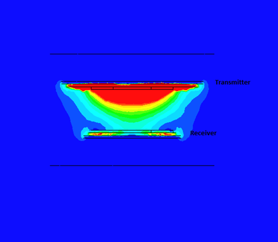
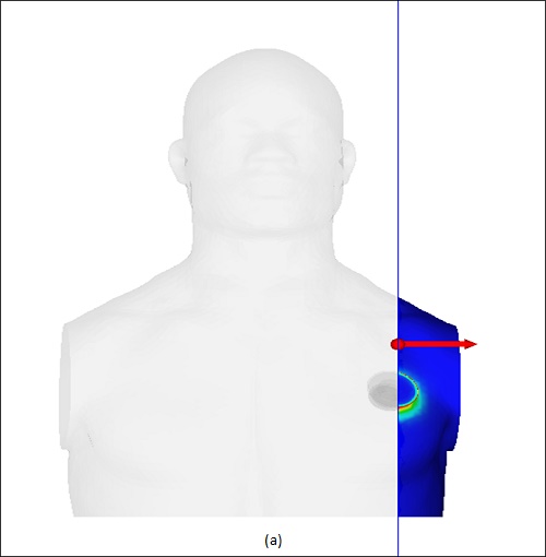
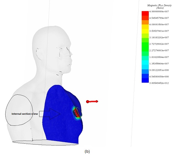
Figures 19a) and 19b) display cross-sectional views of the magnetic flux distribution within the human body. The flux is predominantly concentrated around the receiver due to the shielding components. The maximum magnetic field strength is a few microtesla, well below the standard limit of 27 microtesla published in [11].
Conclusion
This application note explores the innovative realm of Wireless Power Transfer (WPT), showcasing its transformative impact on technology and everyday life. It delves into the principles of Inductive Power Transfer (IPT), a key method of WPT, which utilizes a transmitter and receiver winding to form a transformer with an air gap, facilitating the wireless transmission of power across various applications, notably in electric vehicles and wearable or implanted medical devices (WIMD).
The focus on electric vehicle charging and medical devices like pacemakers illustrates IPT's versatility and its potential to revolutionize energy consumption and healthcare. The study presents a detailed analysis of a WPT system designed for pacemaker battery charging, operating at a low frequency to comply with EMF standards while optimizing system efficiency through the use of aluminum plates and ferrite cores.
Through EMS's AC Magnetic module coupled with an external circuit, the study analyzes the system's electromagnetic parameters, demonstrating how shielding components can significantly enhance efficiency and safety. The findings highlight the coupling coefficient's role in determining WPT efficiency, emphasizing the system's peak performance at resonance and its adaptability to human body constraints.
In Conclusion, the application note underscores the significance of WPT in pushing the boundaries of energy transmission and medical technology, pointing towards a future where power delivery is more seamless and integrated into our daily lives, thereby supporting the ongoing shift towards renewable energy and advanced medical care.
References
[1]:https://www.allaboutcircuits.com/technical-articles/introduction-to-wireless-power-transfer-wpt/
[2] : https://www.we-online.com/web/en/passive_components_custom_magnetics/blog_pbcm/blog_detail_electronics_in_action_100414.php
[3] :https://www.edgefxkits.com/blog/wireless-power-transfer/
[4] :https://en.tdk-electronics.tdk.com/tdk-en/373562/tech-library/articles/applications---cases/applications---cases/thin-and-efficient-power-transmission/980554
[5]: Wireless Power Transmission to Charge Pacemaker Battery, Qazi Saeed Ahmad1Tarana A.Chandel2 , Saif Ahmad3 Department of Electronics & Communication Engg.IntegralUniv.Lucknow,India
[6]: Wireless power transfer for a pacemaker application, Vladimir Vulfin, Shai Sayfan-Altman & Reuven Ianconescu, Journal of Medical Engineering & Technology.
[7]:https://www.dailymail.co.uk/sciencetech/article-4575120/Battery-pacemaker-end-battery-replacement-surgery.html
[8]:Human Exposure to Close-Range Resonant Wireless Power Transfer Systems as a Function of Design Parameters, Xi Lin Chen, Aghuinyue E. Umenei, David W. Baarman, Nicolas Chavannes, Valerio De Santis, Juan R. Mosig, and Niels Kuster, IEEE TRANSACTIONS ON ELECTROMAGNETIC COMPATIBILITY
[9]Design and Evaluation of a Wireless Power Transfer System with Road Embedded Transmitter Coils for Dynamic Charging of Electric Vehicles, KraisornThrongnumchai , Akihiro Hanamura , Yuji Naruse , Kazuhiro Takeda, EV System Lab., Nissan Research Center, Nissan Motor co., ltd., 1-1, Morinosatoaoyama, Atsugi-shi, Kanagawa 243-0123, JAPAN. World Electric Vehicle Journal Vol. 6 - ISSN 2032-6653 - © 2013 WEVA Page
[10]: Wireless (Power Transfer) Transmission of Electrical Energy (Electricity) Intended for Consumer Purposes up to 50 W, Marek PIRI, Pavol SPANIK, Michal FRIVALDSKY, Anna KONDELOVA. POWER ENGINEERING AND ELECTRICAL ENGINEERING VOLUME: 14 | NUMBER: 1 | 2016 | MARCH
[11]: ICNIRP GUIDELINES FOR LIMITING EXPOSURE TO TIME?VARYING ELECTRIC AND MAGNETIC FIELDS (1HZ – 100 kHZ)