Enhancing Horn Antennas with Bi-Omega Particles for Advanced Self-Filtering
Self-Filtering Horn Antenna
In this example, we introduce a self-filtering horn antenna designed for satellite communications. The antenna features a WR-62 (15.8 x 7.9) radiator and achieves self-filtering capabilities through strategically placed bi-omega particles within the waveguide. These particles enable the antenna to operate within an extremely narrow bandwidth centered around 12.6 GHz, maintaining radiation performance similar to a WR-62 radiator. Subsequent figures illustrate the antenna's structure and the slab used in this design.
.jpg)
Figure 1 - the structure's 3D view in SolidWorks
.jpg)
Figure 2 - the structure's dimensions
.jpg)
Figure 3 - The bi-omega particles' structure
Simulation
Loads/ Restraints
The antenna consists of 1 mm thick Perfect Electric Conductor (PEC) metal. The port is positioned on the lateral small face of the horn antenna. The omega particles are represented as PEC material printed on a GML 2032 body with dielectric properties (Er=3.2; Tand=0.0029).
.jpg)
.jpg)
.jpg)
The antenna's port The conductor on the slabThe slab through the screen's slit
Mesh
To ensure accurate meshing, it's essential to maintain mesh element sizes below one-tenth of the free space wavelength. For the slab's conductor, which has a thin thickness of 35 microns and curved shapes, a finer mesh is necessary to capture details effectively.
Results
.jpg)
Figure 4 - Simulated return loss (HFWorks)
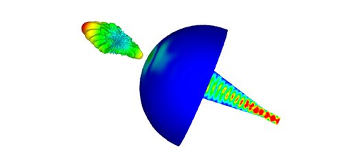
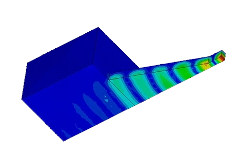
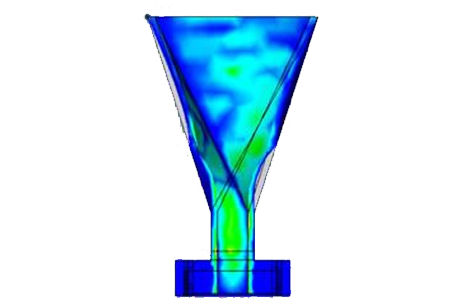
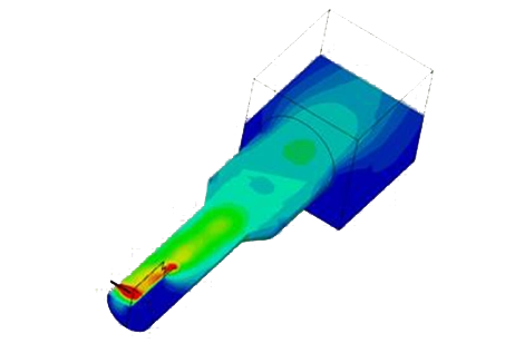
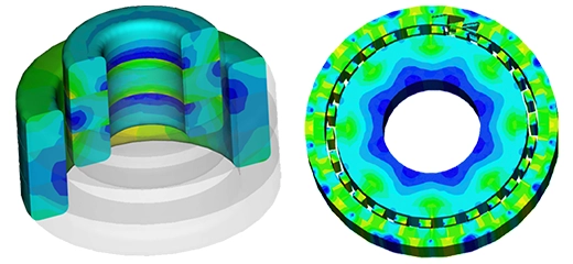
HFWorks offers the section clipping feature, allowing us to visualize the electric field distribution within specific inner areas at the desired frequency. Additionally, it enables viewing the electric field on isolated parts or bodies for detailed analysis.
.jpg)

Figure 5 - Electric field inner distribution
The results have been consolidated into a single plot for easy comparison between HFWorks' simulations and measurements. This plot prominently showcases the filtering function of the bi-omega particles.
.jpg)
Figure 6 - Simulated and Measured return loss
The simulated results, as evident, align closely with the measured data [1]. It's worth mentioning that we employed the Scattering Parameters solver to calculate the return loss. Additionally, the Antenna solver can be utilized to generate radiation patterns and compute various antenna parameters such as gain and axial ratio, if desired.
Conclusion
References
[1] Self-Filtering Low-Noise Horn Antenna for Satellite Applications Filiberto Bilotti, Senior Member, IEEE, Luca Di Palma, Davide Ramaccia, and Alessandro Toscano, Senior Member, IEEE