Rotor Eccentricity Effects on Nissan Leaf Electric Motor Performance
Eccentricity
Motor manufacturers are deeply concerned about eccentricity, which occurs when the rotor's centerline differs from the stator's. Eccentricity parameterization is vital for characterizing and quantifying this fault, considering factors like magnitude, position, and type. Neglecting any parameter can lead to incomplete analysis, undermining understanding and performance assessment. Hence, equal attention to all parameters is crucial for an accurate evaluation of the eccentricity fault's impact on motor performance.
Causes
There can be several causes of eccentricity in a motor, including:
| Manufacturing Defects | Eccentricity can result from manufacturing errors, such as misalignment of motor parts during assembly or inaccurate machining of the rotor or stator components. |
| Mechanical Stress | External mechanical forces or excessive mechanical stress on the motor, such as impacts, vibrations, or improper handling during installation. |
| Bearing Wear | Worn-out or damaged bearings can introduce eccentricity in a motor. Bearings are responsible for maintaining the precise alignment of the rotor within the stator. The rotor can become eccentric if the bearings degrade or fail [1]. |
| Thermal Effects | Temperature variations can cause the expansion or contraction of motor components, which may lead to changes in the rotor's position [2]. |
| Voltage Imbalance | Voltage imbalances between the phases can cause uneven magnetic forces, resulting in eccentricity. Imbalanced voltages can be caused by faulty power supply connections, unbalanced loads, or issues with the motor's internal connections. |
| Rotor Core Faults | Damage or deformations in the rotor core, such as shorted laminations or broken rotor bars, can induce eccentricity. |
Table 1. Eccentricity Causes
Detecting and correcting eccentricity early is crucial to prevent further damage to the motor. Manufacturers employ various techniques and measures to minimize and control eccentricity during the manufacturing process including vibration analysis, visual inspections, electrical measurements such as motor current signature analysis (MCSA), and thermal imaging. All these methods can help to identify and rectify eccentricity issues promptly.
Design Challenges
The most common design challenges are listed below:
-
Simulating an Interior Permanent Magnet Synchronous Motor (IPMSM) designed for electric vehicle application.
-
Parametrizing the static, dynamic, and mixed eccentricity studies.
-
Analyzing and comparing the effect of the eccentricity on the motor performances at load conditions.
-
Checking the radial force variation.
-
Checking the torque and the flux density mapping.
Design Specifications
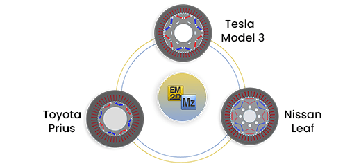
The considered machine is a Nissan Leaf model, where the details are listed below:
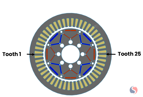
Fig. 1. Nissan Leaf Motor
| Specifications | Value |
| Configuration | 48 slots/ 8 poles |
| Slot Type | Single |
| Based Speed | 750 rpm |
| Rotor Position | Inner |
| Stator OD | 198 mm |
| Stack Length | 150 mm |
| Coil Excitation | 250 A |
Table 2. Motor Characteristics
Static Eccentricity
Static eccentricity refers to a fixed deviation of the rotor from the centerline of the stator. It occurs when the rotor's centerline does not align perfectly with the centerline of the stator.
Two inputs that define the static eccentricity center are parametrized in the next steps: the static distance that determines the position of the static center regarding the motor origin and the static angular that fixes the orientation of the static center or its position regarding the y-axis.
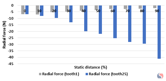
Fig. 2. Radial Force Amplitude versus Static Distance Variation along X-Axis
When the static distance along the x-axis increases, the air gap becomes non-uniform. It starts increasing in the tooth 1 side and decreasing in the opposite direction. This leads to unbalanced force distribution. As the rotor moves away from tooth1, the stator winding / permanent magnet interaction becomes less, which makes the magnetic field weaker and results in decreasing radial force. Conversely, tooth 25, which is diametrically opposite to tooth 1, experiences an increase in radial force when increasing static distance.
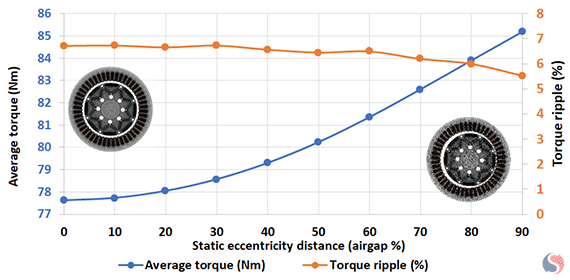
Fig. 3. Radial Force Amplitude versus Static Distance Variation along X-Axis
During the eccentric rotation, the magnetic flux density is higher in some regions and lower in others compared to a perfectly centered rotor. The regions with higher flux density contribute more to the overall torque generation. As a result, the average electromagnetic torque increases when the rotor is eccentric because more torque is produced by the regions with higher flux density, as shown in Figure 3.
A torque ripple is a fluctuation in the output torque of the motor as it rotates. It is an undesirable characteristic as it can cause mechanical vibrations and acoustic noise. Torque ripple is primarily caused by the interaction of multiple harmonics in the motor's magnetic field. When the rotor is perfectly centered, the magnetic field distribution is symmetric, and the harmonics tend to cancel each other out to some extent, resulting in a lower torque ripple. However, with an increase in rotor eccentricity, the magnetic field distribution becomes asymmetric. This can lead to better harmonics cancellation and reduced torque ripple, as illustrated in Figure 3.
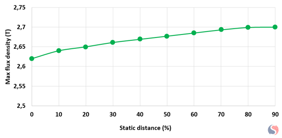
Fig. 4. Maximum Flux Density for each Static Distance
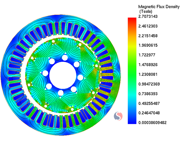
Fig. 5. Magnetic Flux Density Distribution for 90% Static Distance
In the regions where the air gap is smaller due to eccentricity, the magnetic flux density tends to be higher, as mentioned in Figure 4. Conversely, in regions where the air gap is larger, the magnetic flux density tends to be lower. This non-uniformity in the flux density distribution (Figure 5) is a consequence of eccentricity.
Static Eccentricity – 50 % Static Distance
In this section, we fix the static center radial distance at 50 % of the air gap, and we aim to check the impact of varying the angular position of the static center on the radial force of the two diametrical opposite teeth 1 and 25 as defined before.
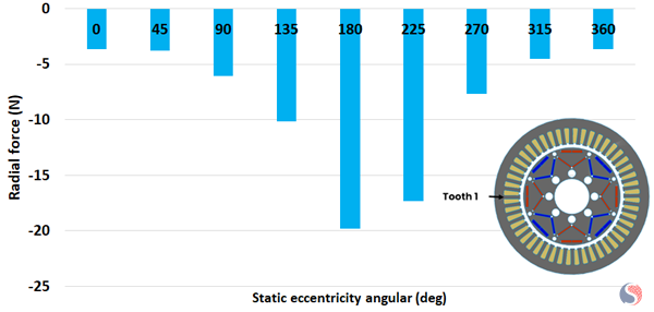
Fig. 6. Tooth 1 Maximum Radial Force for Different Static Angular Positions
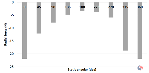
Fig. 7. Tooth 25 Maximum Radial Force for Different Static Angular Positions
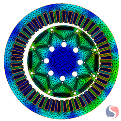
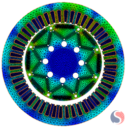
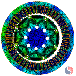
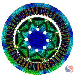
For 0, 180 deg, and 360 deg, the static center is positioned along the x-axis direction. For 90 deg and 270 deg, the static center is located along the y-axis direction.
 |
 |
 |
 |
|
0 and 360 Deg |
90 Deg |
180 Deg |
270 Deg |
The radial force is directly impacted by the air gap length. The larger the air gap, the lower the radial force, and vice versa. From 0 to 180 deg, the static center becomes closer to the tooth 1 area, which makes the predicted radial force increase at tooth 1 and achieves the maximum when the static center is aligned with it, as illustrated in Figure 6. However, the air gap becomes larger in the 25-tooth area, which explains the decrease of the radial force there, as shown in Figure 7. Coming back to the positive x-axis alignment, from 180 degrees to 360 degrees, the radial force increases in the 25-tooth zone and decreases in the diametrical opposite motor side.
Dynamic Eccentricity
Dynamic eccentricity refers to a condition where the rotor's center of mass does not align with the geometric center of rotation, causing a varying offset as the motor rotates.
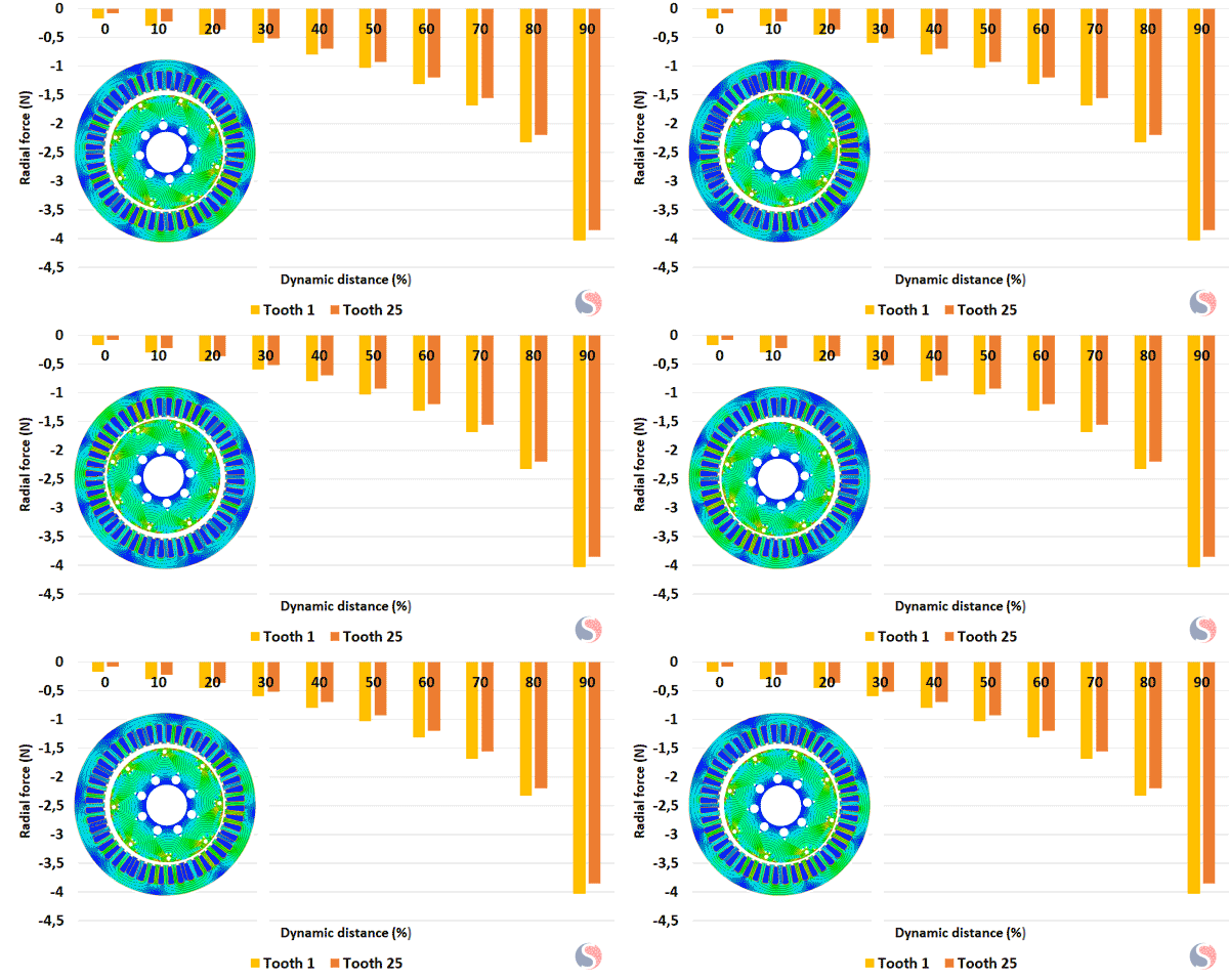
Fig. 8. Radial Force Calculated at Teeth 1 and 25 for Different Dynamic Distances
From Figure 8 one can notice that the peak tooth radial force is the same on all the teeth but occurs at different time instances during each rotation. During each revolution of the rotor, the maximum radial force acting on the stator teeth occurs when the eccentricity aligns with a particular stator tooth. At this point, the air gap is minimized, resulting in a stronger magnetic field and a higher magnetic force on that specific tooth. However, since the dynamic eccentricity continuously changes the relative position between the rotor and stator, the peak tooth radial force occurs at different time instances for each tooth throughout a complete rotation. This means that each tooth experiences the maximum radial force at a different point in time during each revolution.
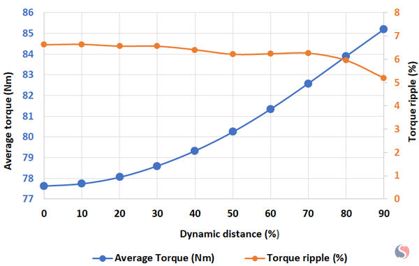
Fig. 9. Average Torque and Torque Ripple for Different Dynamic Distance
The previously discussed observations regarding average electromagnetic torque and torque ripple in static eccentricity can be applied to similar situations. Specifically, the average torque experiences an increase, while the torque ripple decreases as depicted in Figure 9.
Mixed eccentricity
Mixed eccentricity is a combination of static and dynamic eccentricity. It occurs when there is both a constant offset between the rotor and stator (static eccentricity) as well as a varying offset during rotation (dynamic eccentricity).
In the following graph, the dynamic distance is fixed at 50 % and the static distance varies from 10 % to 40 % of the air gap length.
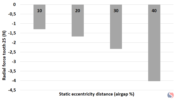
Fig. 10. Radial Force Prediction for Different Static Distances at Mixed Eccentricity Case
In the next graph, the static distance is fixed at 50 % and the dynamic distance varies from 10 % to 40 % of the air gap length.
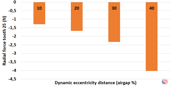
Fig. 11. Radial Force Prediction for Different Dynamic Distances at Mixed Eccentricity Case
In both analyses, when increasing the static distance or the dynamic distance, the magnetic strength calculated at tooth 25 is increasing, leading to a rise in the radial force.
Conclusion
Considering this study, the EMWorks2D platform was investigated to predict the performances of a Nissan Leaf motor when subjected to eccentricity fault during on-load operation. A parametrization-based eccentricity input was established to understand the physics needed to explain and analyze the motor's behavior under such fault conditions. EMWorks2D provides a standardized framework for studying eccentricity faults and enables researchers and engineers to assess the impact of eccentricity on motor performance, efficiency, and reliability. Furthermore, parametrization facilitates the development of diagnostic and predictive tools that can detect and anticipate eccentricity-related issues in motors, allowing for timely maintenance and improved motor performance.
References
[1] Li, J. T., Z. J. Liu, and L. H. A. Nay. "Effect of radial magnetic forces in permanent magnet motors with rotor eccentricity." IEEE Transactions on Magnetics 43, no. 6 (2007): 2525-2527.
[2] Hong, Jongman, Sanguk Park, Doosoo Hyun, Tae-june Kang, Sang Bin Lee, Christian Kral, and Anton Haumer. "Detection and classification of rotor demagnetization and eccentricity faults for PM synchronous motors." IEEE Transactions on Industry Applications 48, no. 3 (2012): 923-932.


