5G Antenna Simulation
The demand for high-speed mobile communication drives the need for 5G antenna development, using tools like HFWorks for simulation. This enables the design of Dual-Band mm-wave antennas critical for 5G's ultra-fast data transmission. By addressing mm-wave frequency challenges, HFWorks aids in optimizing antenna design for a wide range of 5G applications, making it a cornerstone in advancing toward the next generation of mobile communications.
CAD 5G Antenna Model
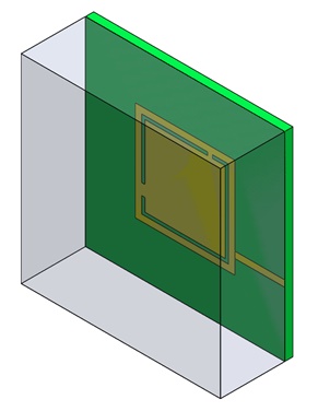
Figure 1 - 3D model of Dual Band antenna for 5G applications
This description highlights the design of a Dual-Band mm-wave antenna tailored for 5G networks, emphasizing its innovative features. The antenna incorporates L-shaped slots on a square patch, enhancing its capacitive and inductive properties to hit resonant frequencies at 28 GHz and 38 GHz. This design, utilizing RT/Duroid with specific electrical properties, is optimized for minimal energy loss and high signal integrity at mm-wave frequencies. A microstrip feed line of 0.2mm width achieves an impedance of 100 Ohms, ensuring efficient performance. The detailed geometrical parameters underscore the precision required in designing antennas for the next generation of mobile communications, reflecting a blend of advanced engineering and materials science.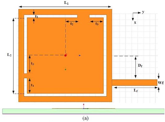
| Variable | Value |
| L1 | 3.1 |
| L2 | 2.5 |
| t1 | 0.1 |
| t2 | 2.7 |
| t3 | 0.4 |
| t4 | 0.4 |
| t5 | 0.5 |
| Lf | 1.5 |
| Wf | 0.2 |
| Df | 0.9 |
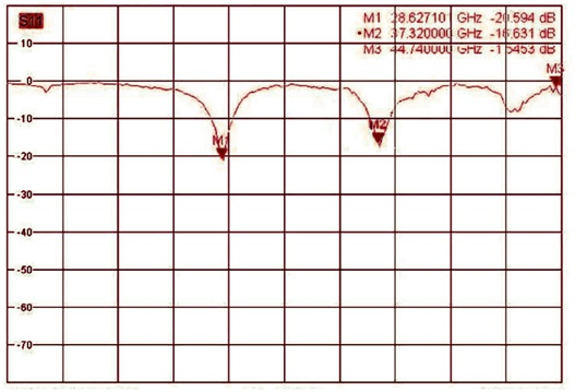
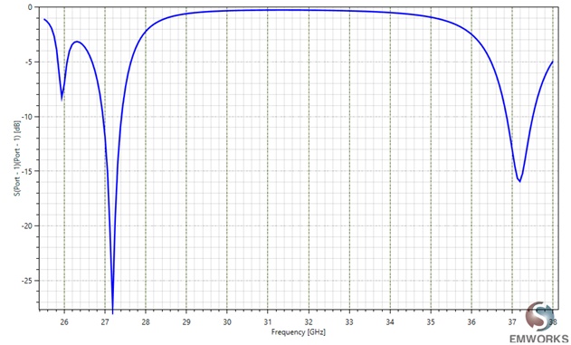
S-Parameters of the 5G antenna
Figure 3 displays S-Parameters for the patch antenna, comparing HFWorks simulations with actual measurements. It highlights resonant frequencies at 27.375GHz (-29.87dB reflection coefficient) and 37.125GHz (-16.39dB), showcasing the antenna's performance at key 5G bands.
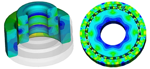
Gain of the 5G antenna
The far field simulation shows the distribution of the field around the model at a distance from the structure. Figure 4 (a) illustrates the gain pattern in a 3D format at the first resonance frequency of 27.375 GHz, and Figure 4 (b) shows the same gain pattern in a 2D format.
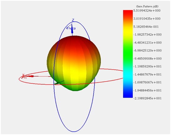 Figure 4-a
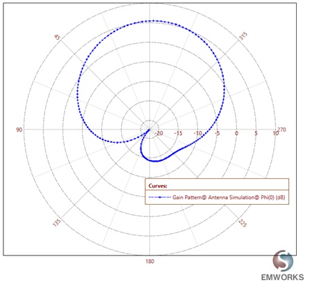 Figure 4-b