Innovating Diplexer Design
Diplexers, critical in satellite communications and
cellular networks for splitting or combining frequency bands, traditionally
rely on external junctions like T-junctions or circulators for integration.
This conventional method involves connecting two filters to distribute energy
externally. However, we introduce a paradigm shift by eliminating these
external junctions in favor of incorporating resonators directly into the
diplexer. This not only streamlines the design process but also improves
performance by adding resonant poles into the diplexer’s framework, marking a
significant advancement in diplexer technology.
This blog details the creation and testing of an advanced 10-pole diplexer, showcasing the latest in RF engineering to improve communication system signal processing. The design cleverly combines poles from different filters: two from a dual-band filter, four aimed at the Tx bandpass filter, and four dedicated to the Rx bandpass filter. The core technology behind this innovation involves asynchronously tuned microstrip square open-loop resonators. This approach enhances the diplexer's frequency response precision, optimizing its performance for sophisticated transmitting and receiving functions, and exemplifies a leap forward in diplexer design efficiency and effectiveness.
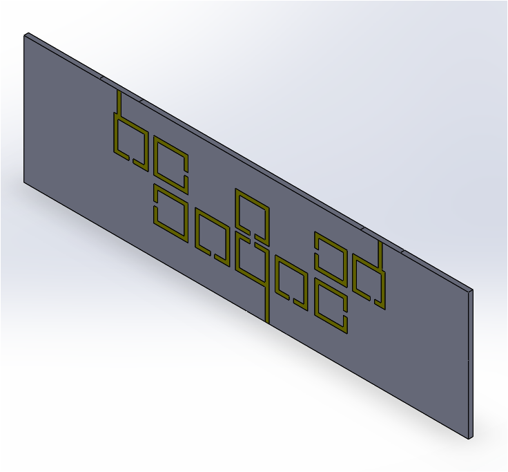
Figure 1- Geometry of Multi-Coupled Resonator Microwave Diplexer
The Design
Journey
Figure 2 reveals the intricate layout of a diplexer, characterized by its multi-coupled resonator design. This diplexer is engineered for efficiency, with each port being serviced by a 50 microstrip-line, measuring a width of 1.1 mm, and operating at a central frequency of 1.84 GHz. The choice of material, RT/Duroid 6010LM, is notable for its dielectric constant of 10.8, a low loss tangent of 0.0023, and a thickness of 1.27 mm, ensuring optimal performance during simulation. The design intricacies, including the geometrical parameters of the diplexer’s multi-coupled resonators, are meticulously cataloged to streamline the design process, reflecting a blend of precision and practicality in the development workflow.
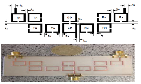
Figure2 - Diplexer layout and fabricated model [1]
The following table encapsulates the various dimensions (global variables) that are meticulously prepared for importation into the design process, ensuring a seamless and efficient workflow:
|
Dimension |
Value (mm) |
|
S1 |
1.5 |
|
S2 |
2 |
|
S3 |
2 |
|
S4 |
1.6 |
|
S5 |
0.9 |
|
S6 |
1.65 |
|
S7 |
1.95 |
|
S8 |
2 |
|
S9 |
1.45 |
|
t1 |
1.45 |
|
t2 |
1.35 |
Table 1 - summarizes the list of dimensions to be imported into SolidWorks
This structured compilation of dimensions serves as the foundation for the design, facilitating an expedited and accurate development process.
A Symphony of
Results
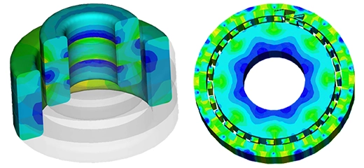
The simulation of the diplexer circuit model was meticulously conducted
using HFWorks for S-Parameters analysis. Figure 3 illustrates the electric
field distribution across the device, offering insights into how the field
interacts within the structure. Meanwhile, Figure 4 presents the S-parameters
simulation results, providing a detailed view of the performance
characteristics of the Multi-Coupled Resonator Microwave Diplexer. These
figures are pivotal in understanding the device's operational efficacy and its
electromagnetic properties.

Figure3 - Distribution of the electric field at 1.9GHz

Figure 4 - Simulation responses of the diplexer circuit model with HFWorks
 results of the diplexer circuit model")
Figure 5 - Measured and simulated (with ADS) results of the diplexer circuit model
The measured outcomes alongside the electromagnetic (EM) loss simulation results obtained with HFWorks are displayed in Figure 4, revealing that the isolation between the transmit (Tx) and receive (Rx) bands is approximately 40 dB. The comparison between these graphs demonstrates a notable concordance between the simulation data and the actual measurements, affirming the accuracy of the simulations in predicting the diplexer's performance.
Conclusion
REFERENCES
[1] Augustine O. Nwajana, Kenneth S. K. Yeo, " Multi-Coupled Resonator Microwave Diplexer with High Isolation", 2016 European Microwave Conference, pp. 1167-1170, 4–6 Oct 2016, London, UK.