How to Reduce Stray Losses in Power Transformers with Magnetic Shunts and Autodesk Inventor
Kousseil Ben Ahmed . May 30, 2024
Stray Losses in Power Transformers
Stray losses in power transformers are energy losses that occur outside the core and windings, primarily due to leakage flux. These losses arise from eddy currents induced in the transformer’s structural parts, such as the tank, core clamps, and other metallic components. Stray losses contribute to the overall inefficiency of the transformer, causing unwanted heating and potentially impacting its longevity and performance.
Using Magnetic Wall Shunts to Reduce Stray Losses
Magnetic wall shunts effectively reduce stray losses in power transformers by redirecting leakage flux away from the tank and structural components. This prevents eddy currents in non-functional metallic parts, minimizing unwanted heating and energy dissipation. The use of magnetic wall shunts enhances transformer efficiency and longevity, while also improving thermal management and reducing the risk of hot spots.
Vertical Magnetic Wall Shunts
Design Challenges of Magnetic Wall Shunts
Designing magnetic wall shunts to reduce stray losses in power transformers involves several challenges. Accurate placement and sizing of shunts require detailed modeling of magnetic fields and leakage flux paths. The shunts must effectively redirect flux without adding losses or interfering with transformer functions. Selecting the right materials, balancing magnetic permeability, mechanical strength, and cost is crucial. Additionally, integrating shunts into the existing design without significantly increasing size, weight, or complexity is essential for maximizing efficiency and longevity. Using advanced simulation tools like EMWORKS powered by Autodesk Inventor can help address these challenges by providing precise modeling and design optimization.
EMWORKS Powered by Autodesk Inventor
EMWORKS powered by Autodesk Inventor is a robust simulation and design tool that significantly aids in the development of magnetic wall shunts for power transformers. This integrated software suite allows engineers to accurately model and analyze the magnetic fields and leakage flux paths within the transformer. With its advanced capabilities, designers can optimize the placement and sizing of magnetic wall shunts to effectively redirect flux, minimizing stray losses and preventing unwanted heating. The combination of EMWORKS and Autodesk Inventor facilitates precise material selection and ensures that the shunts integrate seamlessly into existing transformer designs without adding excessive size, weight, or complexity.
EMWORKS Powered by Autodesk Inventor
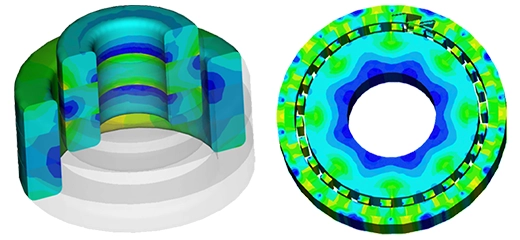
Magnetic Flux Density Plot
EMWORKS provides detailed magnetic flux density plots that are crucial for analyzing the performance of transformer cores. These plots visually represent the distribution and intensity of magnetic flux within the core, allowing engineers to identify areas of high flux concentration that could lead to saturation or excessive losses. By examining the flux density plot, designers can ensure that the core material is optimally utilized and that the magnetic circuit is well-balanced. This analysis helps in making informed decisions about core geometry, material selection, and placement of components to minimize losses and enhance efficiency.
Magnetic Flux Density Plot in Transformer
Eddy-Current Loss Density on Transformer Tank Without Magnetic Shunts
The distribution of eddy-current loss density (W/m³) on a transformer tank without magnetic shunts reveals significant areas of energy dissipation due to induced currents in the tank's metallic components. As visualized in the accompanying plot, high-loss regions are concentrated around areas where the leakage flux is most intense. These eddy currents, generated by the interaction of the magnetic field with the conductive tank walls, lead to localized heating and energy loss. Without magnetic shunts to redirect the leakage flux, these losses can be substantial, impacting the transformer's efficiency and potentially leading to overheating and material degradation.
Eddy-Current Loss Density on Transformer Tank Without Magnetic Shunts
Eddy-Current Loss Density on Transformer Tank With Magnetic Shunts
The distribution of eddy-current loss density (W/m³) on a transformer tank with magnetic shunts shows a marked reduction in energy dissipation compared to configurations without shunts. Magnetic shunts effectively redirect leakage flux away from the tank's metallic components, significantly decreasing the induced eddy currents. As illustrated in the accompanying plot, the high-loss regions are greatly diminished, indicating a lower concentration of eddy-current-induced heating. This reduction in loss density not only enhances the efficiency of the transformer but also mitigates the risk of overheating and material degradation. By integrating magnetic shunts, the transformer's performance and longevity are substantially improved, demonstrating the effectiveness of this solution in managing stray losses.
Eddy-Current Loss Density on Transformer Tank With Magnetic Shunts
Magnetic Flux Distribution in the Magnetic Shunts
The magnetic flux distribution (Tesla) in the magnetic shunts is a critical aspect of their performance in mitigating stray losses in power transformers. The accompanying plot illustrates the concentration and flow of magnetic flux within the shunts. Effective shunt design ensures that the magnetic flux is uniformly distributed, avoiding localized saturation and efficiently redirecting the leakage flux away from non-functional metallic parts of the transformer. By channeling the magnetic flux through these specialized paths, the shunts significantly reduce eddy current formation in the transformer tank, thereby enhancing overall efficiency and reducing unwanted heating. The precise visualization provided by the flux distribution plot is instrumental in optimizing shunt design for maximum performance.
Magnetic Flux Distribution in the Magnetic Shunts
Impact of Magnetic Shunts on Losses
The table illustrates the impact of magnetic shunts on various types of losses in power transformers.
Core Loss: Without shunts, the core loss is 2484 W. With the addition of magnetic shunts, this loss decreases significantly to 1847 W.
Shunt Loss: Introducing magnetic shunts introduces a minor additional loss of 52.75 W.
Tank Loss: The most substantial improvement is seen in tank loss, which drops from 2252 W without shunts to just 254 W with shunts.
These results highlight the effectiveness of magnetic shunts in reducing overall energy dissipation within transformers, enhancing efficiency, and reducing the risk of overheating.
Parameter
Loss Without Shunt
Loss With Shunt
Core Loss (W)
2484
1847
Shunt Loss (W)
52.75
Tank Loss (W)
2252
254
Impact of Magnetic Shunts on Mechanical Forces
The table illustrates the impact of magnetic shunts on mechanical forces within power transformers:
Tank Force: Without shunts, the tank force is 32 N. With the addition of magnetic shunts, this force is dramatically reduced to 0.6 N.
Shunt Force: The introduction of magnetic shunts results in a shunt force of 10 N.
These results demonstrate the effectiveness of magnetic shunts in significantly reducing the mechanical forces exerted on the transformer tank, thereby enhancing structural integrity and reducing stress. The shunt force introduced is well-managed, further contributing to the overall stability and efficiency of the transformer system.
Part
Without Shunt
With Shunt
Tank Force(N)
32
0.6
Shunt Force (N)
10
Implementing magnetic wall shunts in power transformers significantly reduces stray losses by redirecting leakage flux away from non-functional metallic parts. Using advanced tools like EMWORKS powered by Autodesk Inventor, engineers can optimize the design and placement of these shunts, enhancing transformer efficiency and longevity. This approach minimizes energy dissipation and prevents overheating, ensuring a more reliable and durable transformer system.
Share on
By visiting or using this website you agree to the storing of cookies on your device to enhance site navigation,
analyze site usage, and assist in our marketing efforts.
View cookies details.