Effects of 3D and 2D Coil Designs on Induction Heating of a Mold Plate
Induction Heating of Mold Plate
The widespread adoption of electromagnetic induction heating in molds is attributed to its rapid heating and high-efficiency benefits. When integrated with a cooling process, induction heating enables dynamic mold temperature control. This investigation focuses on analyzing the impact of 3D and 2D coil designs on mold plate temperature control. The CAD models of each design are depicted in Figure 2, providing visual representations for comparison and evaluation.
![Induction heating for injection mold plate [1]](/ckfinder/userfiles/images/Induction-heating-for-injection-mold-plate-%5B1%5D.jpg)
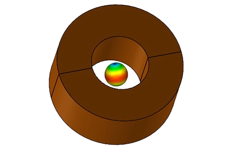
Figure 1 - Induction heating for injection mold plate [1]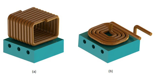
Figure 2 - 3D model of Mold plate with both 3D a) and 2D b) coil
CAD M
The models consist of a square mold plate with three cooling channels located 10 mm below the top surface, and two 8 mm diameter copper inductor coils positioned 3 mm from the mold surface. Refer to Table 1 for dimensions.
The analysis aims to compute temperature distribution across the mold plate to enhance temperature control during the heating process.
Table1 - Components’ dimensions
3D coil | 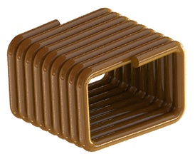 | 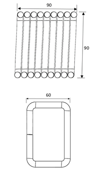 |
2D coil | 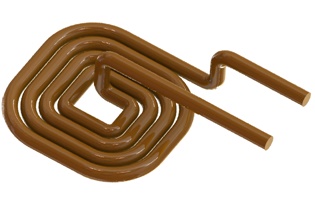 | 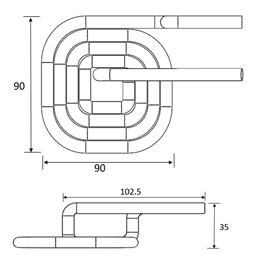 |
Mold plate | 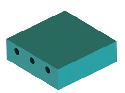 | 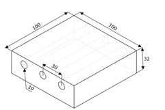 |
Simulation Setup
The induction heating process is simulated in EMS using AC Magnetic module coupled with transient thermal. It is used to compute and visualize the temperature distribution versus time, across the studied mold plate.
The simulation setup consists of the following steps:
1. Select the appropriate materials:
Table2 - Material properties
| Part | Material | Density (Kg/$$ m^3 $$) | Magnetic permeability | Electrical resistivity ($$ \mathbf{m\Omega} $$) | Thermal conductivity (W/m.K) | Specific heat capacity (J/Kg.K) |
| Coil | Copper (Cu) | 8940 | 0.99 | 1.71 E-07 | 400 | 392 |
| Mold | Stainless steel 420 (ISO 683/134) | 7700 | 200 | 5.5 E-07 | 14 | 448 |
2. Electromagnetic Inputs
The inductor coils are solid coils, with the 3D coil having 9 turns and the 2D coil having 4 turns. They are capable of supporting a maximum current of 1500 A rms at a frequency of 75 kHz.
3. Thermal Inputs
The mold plate starts with an initial temperature of 40°C. Thermal convection is applied to the surrounding air at an ambient temperature of 25°C, with a coefficient set at 10 W/m²K.
Meshing
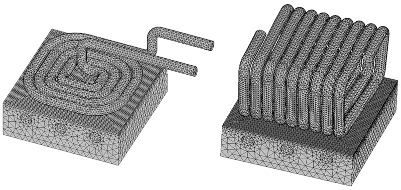
Due to the concentration of eddy currents in the skin depth of the top face of the mold plate, a finer mesh is necessary for precise results. EMS offers a mesh control feature that can be applied to edges, faces, and bodies.
Figure 3 depicts the meshed models with two distinct mesh controls applied to the mold plate face.
Results
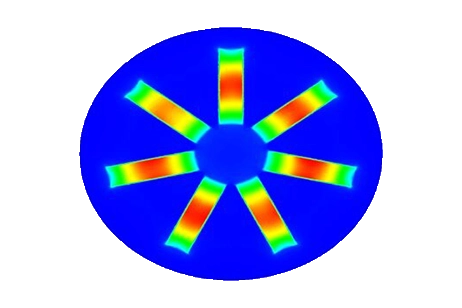
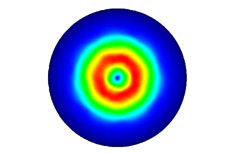
EMS enables prediction and visualization of the temperature distribution across the top surface of the mold plate after 2 seconds of heating for each coil design. For the 3D coil, higher temperature zones are observed in the center of the mold plate, consistent with experimental findings [1]. Conversely, the 2D coil design shows lower temperature values in the center area of the mold plate. This temperature distribution is deemed inadequate for the heating process in the injection molding field..
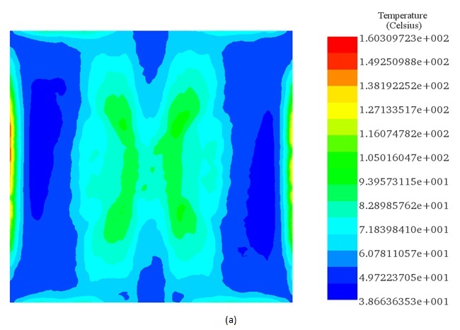
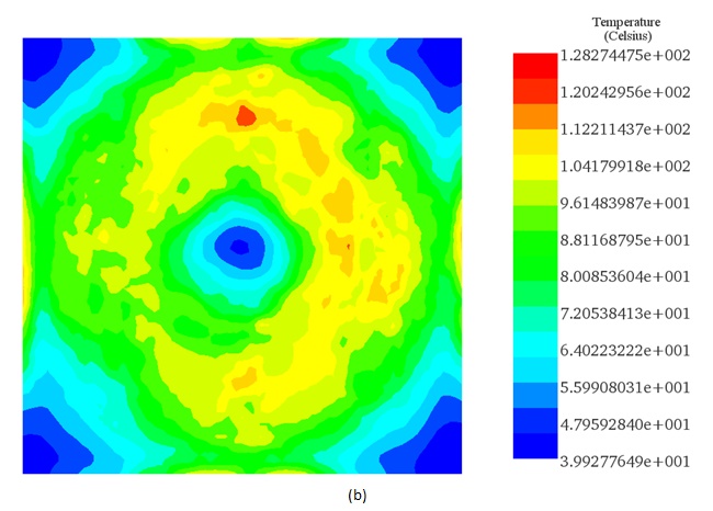
Figure 4 - Temperature distribution across the mold plate for 3D coil a). and 2D coil b) design after 2s of heating.
The figure below illustrates three measuring positions, T1, T2, and T3, located on the top surface of the mold plate.
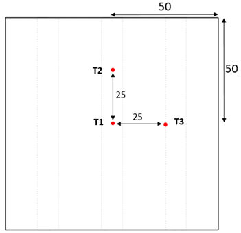
The simulation results obtained from the three measuring points demonstrate that the temperature difference between them is more pronounced in the 2D coil design compared to the 3D coil design. This confirms that the latter is more suitable for mold temperature control via induction heating.
Furthermore, the EMS simulation results closely align with the experimental findings provided by the reference. Table 3 presents a comparison of the EMS results with those from the reference [1].
| Design | Temperature results (°C) | T1 | T2 | T3 |
3D coil | Experimental_ref [1] | 89 | 78.5 | 66.1 |
| Simulation_ref [1] | 91 | 80.1 | 74.04 | |
| EMS | 89 | 63 | 70 | |
2D coil | Experimental_ref [1] | 64 | 108 | 105 |
| Simulation_ref [1] | 50.5 | 111 | 110.6 | |
| EMS | 47.64 | 108.7 | 103 |
Conclusion
The application note investigates the efficacy of electromagnetic induction heating in mold temperature control, particularly examining the influence of 3D and 2D coil designs on mold plate temperature distribution. Utilizing EMS simulation, the study aims to enhance temperature control during the induction heating process. CAD models illustrate the differences between the coil designs, with simulations conducted to compute temperature distributions across the mold plate. Through meticulous analysis, it's observed that the 3D coil design induces higher temperature zones at the mold plate's center, while the 2D coil design yields lower temperature values in the same area. However, the temperature distribution from the 2D coil design is deemed inadequate for injection molding applications. Simulation results are in close agreement with experimental findings, underscoring the accuracy of EMS in modeling electromagnetic phenomena. Additionally, temperature measurements confirm the superiority of the 3D coil design for mold temperature control. This study provides valuable insights into optimizing induction heating processes for mold temperature regulation, essential for enhancing efficiency and performance in various industrial applications.
References
[1]. Minh, Pham Son. "EFFECT OF 2D AND 3D COIL ON THE DYNAMIC MOLD TEMPERATURE CONTROL BY INDUCTION HEATING." Vietnam Journal of Science and Technology 52.4 (2014): 409.


