Optimizing Eddy Current Brakes Using EMWORKS Simulation
Eddy Current Brakes
Eddy current brakes are a vital component in various applications, providing non-contact braking solutions that are highly reliable and efficient. This application note explores the simulation of eddy current braking using EMWORKS software, detailing the process and benefits of utilizing advanced simulation tools to optimize the design and performance of eddy current braking systems.
Eddy Current Braking Principle
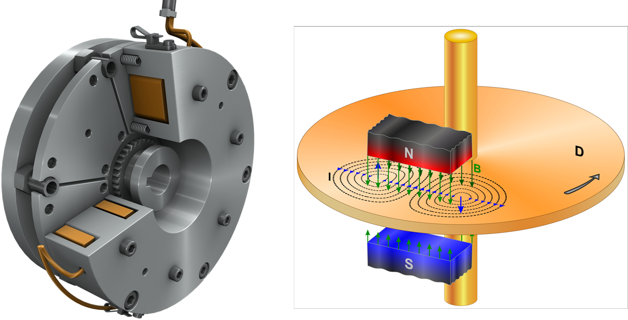
Eddy current brakes utilize electromagnetic fields to decelerate objects without contact. As a conductor moves through a magnetic field, eddy currents are induced, creating an opposing force that slows the object. This non-contact method converts kinetic energy into heat, offering a wear-free alternative to traditional brakes, ideal for applications requiring reliable, maintenance-free operation.
Eddy Current Braking Principle
Eddy Current Braking Design Challenges
Designing an eddy current braking system presents a complex challenge, requiring precise calculations and considerations. Engineers must determine the torque for various system types—passive, active, and hybrid—while accounting for the relationship between braking torque and speed. The choice of magnet type, their arrangement, and the number of poles significantly influence the braking force. Additionally, the excitation current plays a crucial role in modulating the braking torque. Effective design also involves managing the deceleration torque to ensure smooth operation, as well as calculating the dissipated power to prevent energy waste. A critical aspect is monitoring the temperature rise in conductive parts, which could impact performance and longevity. Each factor interplays to create a reliable and efficient braking system.
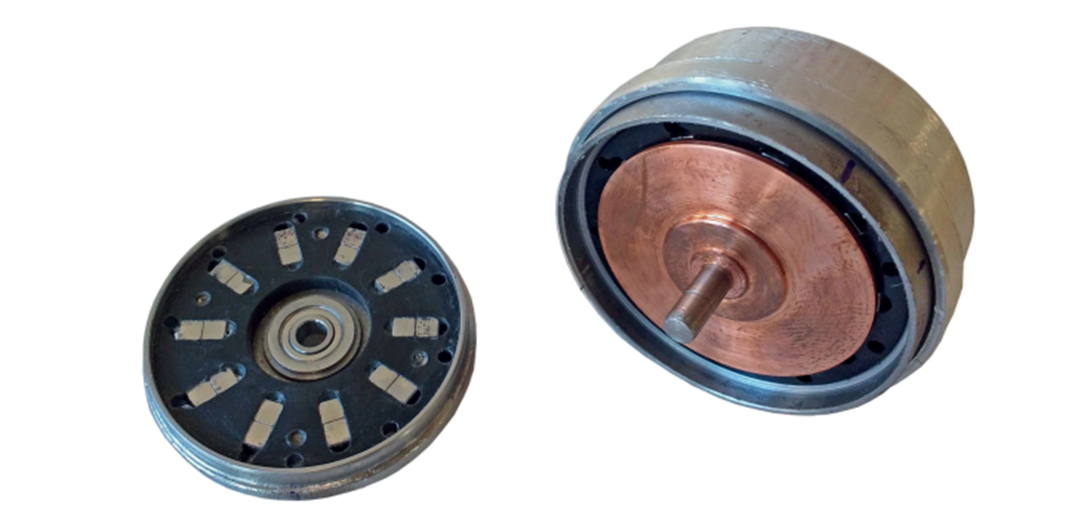
Image of an actual eddy current brake
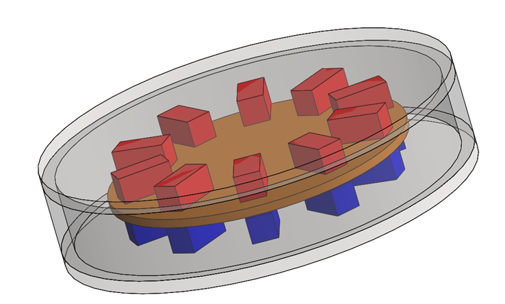
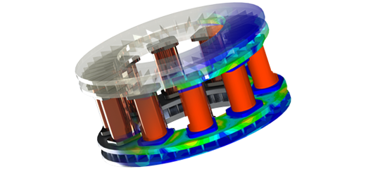
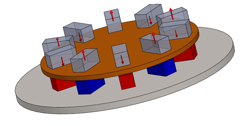
Model of an eddy current brake with same direction magnets
EMWORKS Simulation Results
An axial permanent magnet brake: same direction magnets
An axial permanent magnet braking system uses permanent magnets arranged axially, all oriented in the same direction, to induce eddy currents in a rotor. This configuration provides contactless braking with consistent force and low maintenance. EMWORKS is utilized to simulate this system, with the results presented below.
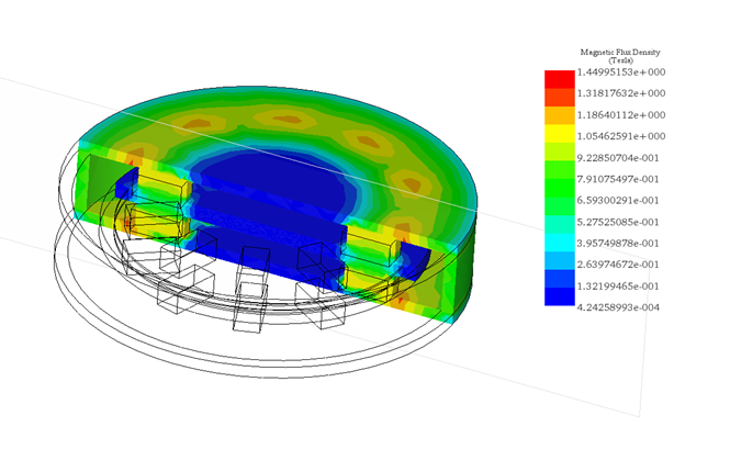
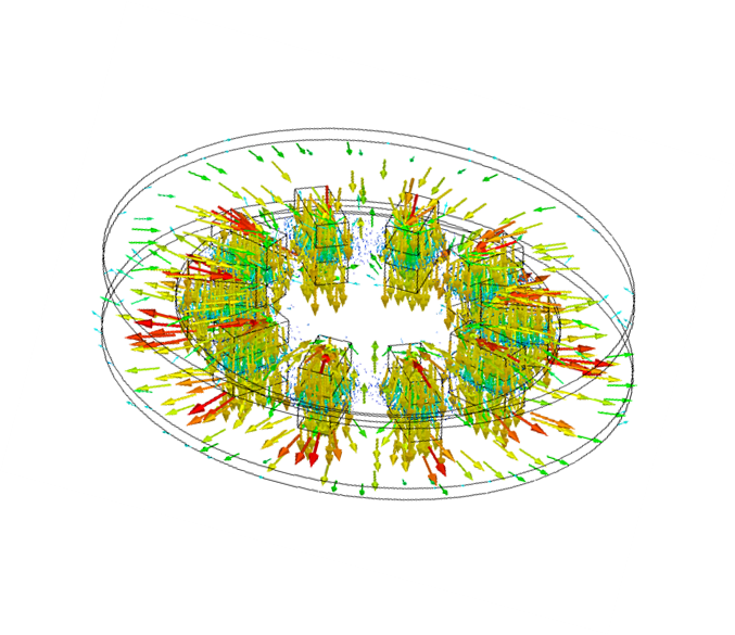
Magnetic flux density within the brake
Magnetic Flux Density Within the Brake
The figures above illustrate the magnetic flux density within an axial permanent magnet braking system using fringe and vector plots for enhanced visualization. These plots clearly show the magnetic field circulating through the back and lateral iron components, forming two complete loops. Each loop contains a pair of poles, creating a symmetrical magnetic circuit essential for the system's effective braking capabilities. This detailed visualization is crucial for optimizing the system's design to ensure peak performance.
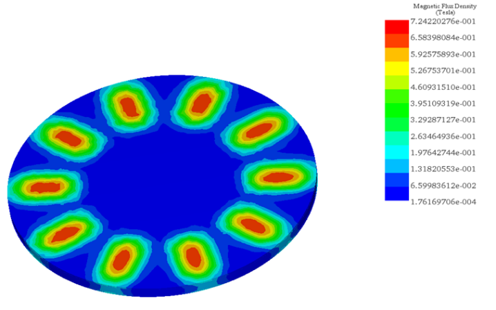
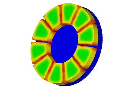
Magnetic flux density across the copper disk
Magnetic Flux Density Across the Copper Disk
The figures above illustrate the magnetic flux density across the copper disk, revealing ten distinct loops. Each loop is strategically positioned between two magnetic poles, showcasing a precise and orderly magnetic field distribution critical for the braking system's functionality. This arrangement ensures an even application of the eddy current braking effect, enhancing the system's efficiency and reliability.
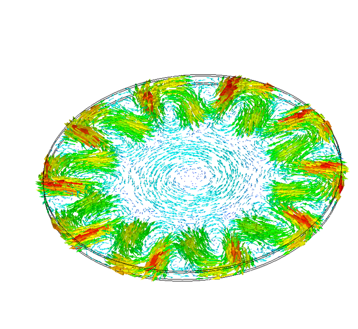
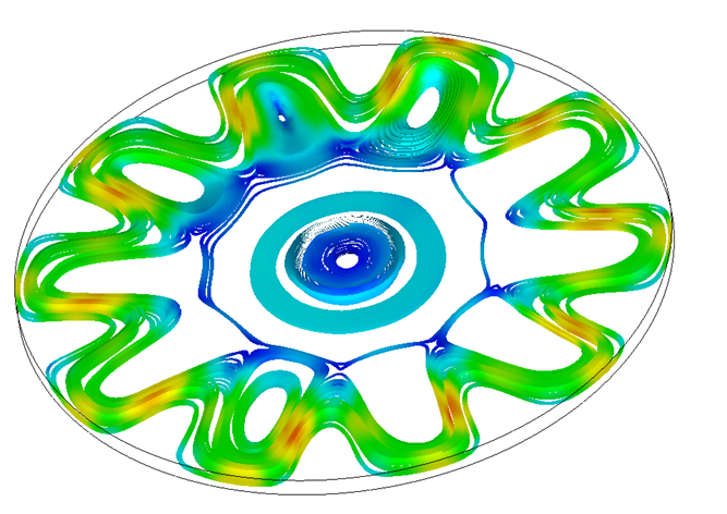
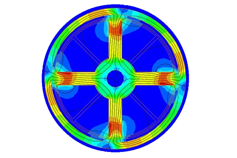
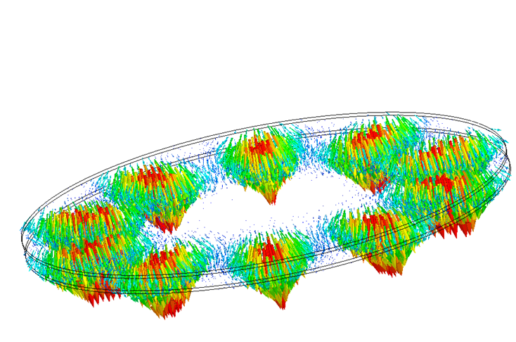
Eddy current density across the copper disk
Eddy Current Density Across the Copper Disk
The rotation of the copper disc within the magnetic field created between both stator sides generates induced eddy currents in the disc. These eddy currents are strongest between the magnetic poles, as evident from the simulation results above. This concentration of eddy currents is crucial for the braking system's efficiency, providing a consistent and reliable braking force. The detailed visual representation in the simulation highlights the precise distribution and intensity of these currents, showcasing the system's optimal design and functionality.

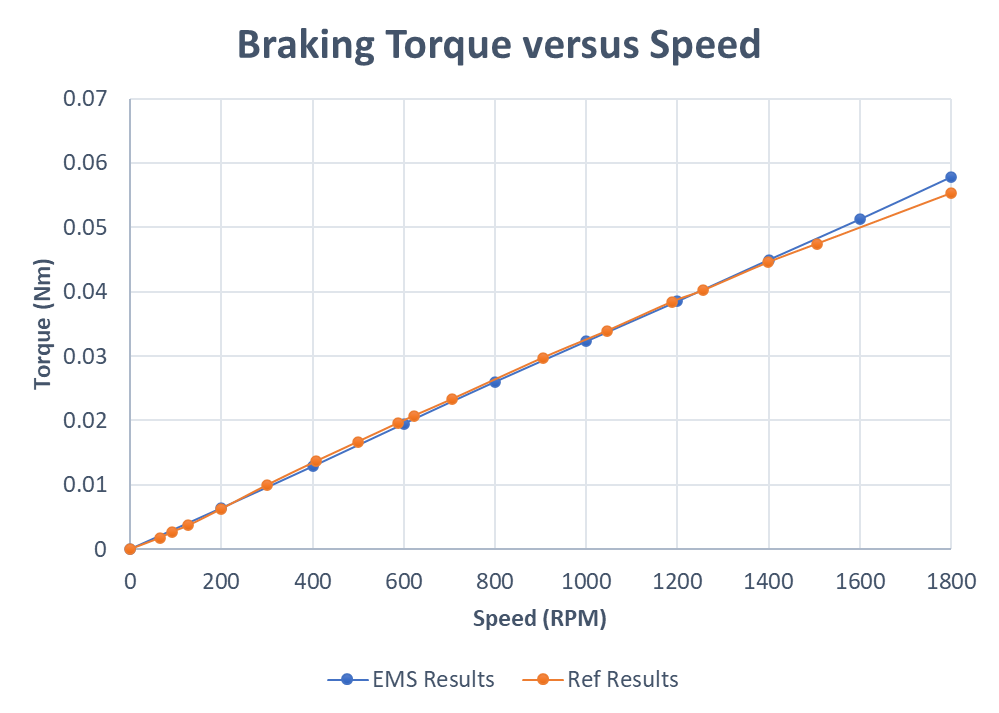
Braking Torque Vs Rotor Speed
Braking Torque vs. Rotor Speed
The eddy currents act in the opposite direction to the motion. Consequently, the generated torque, specifically the braking torque, opposes the disc's rotation, tending to stop it. The figure above shows the variation of the torque versus rotor speed, indicating that the torque increases with speed. This relationship is crucial for understanding and optimizing the braking system's performance. The comparison against the experimental data is also included, showing a good agreement.
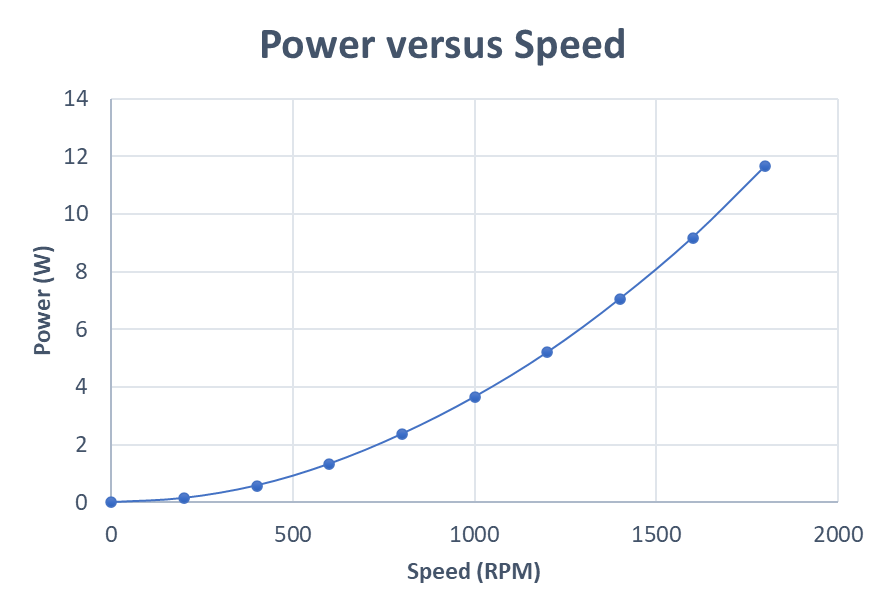
Dissipated Power vs. Rotor Speed
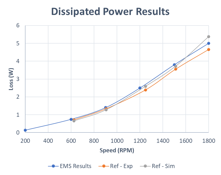
The Dissipated Power Vs Rotor Speed
The dissipated power in the disc is a critical factor in the braking system's performance. As the rotor speed increases, the induced eddy currents generate more heat, leading to higher power dissipation. The figure above illustrates the variation of dissipated power versus rotor speed, demonstrating that dissipated power increases with speed. This relationship is essential for assessing the thermal management needs of the system and ensuring its reliability. The comparison against experimental data shows a good agreement, validating the simulation results and confirming the system's design efficiency.
An axial permanent magnet brake: alternating direction magnets
Model of an eddy current brake with alternating direction magnets
In this case, the magnets have alternating magnetization, eliminating the need for the cylindrical iron part that closes the magnetic path in the same-direction magnet configuration. We now have one magnetic loop: from one pole to another on the same stator side, then through the air gap and copper disc to the opposite stator side. This configuration increases the magnetic field passing through the copper disc and reduces the amount of steel required, making the system lighter.
Braking Torque Vs Rotor Speed for the Alternating Magnets Configuration
Power Vs Rotor Speed for the Alternating Magnets Configuration
Braking Torque vs. Rotor Speed
As illustrated above, the alternating magnet configuration has significantly improved the braking torque of our system. By optimizing the magnetic loop from one pole to another on the same stator side, and then through the air gap and copper disc to the opposite stator side, we have enhanced the magnetic field's strength and distribution. This improvement not only increases the braking torque but also contributes to the overall efficiency and performance of the system. This optimized configuration demonstrates the effectiveness of the alternating magnets arrangement in achieving better braking capabilities.
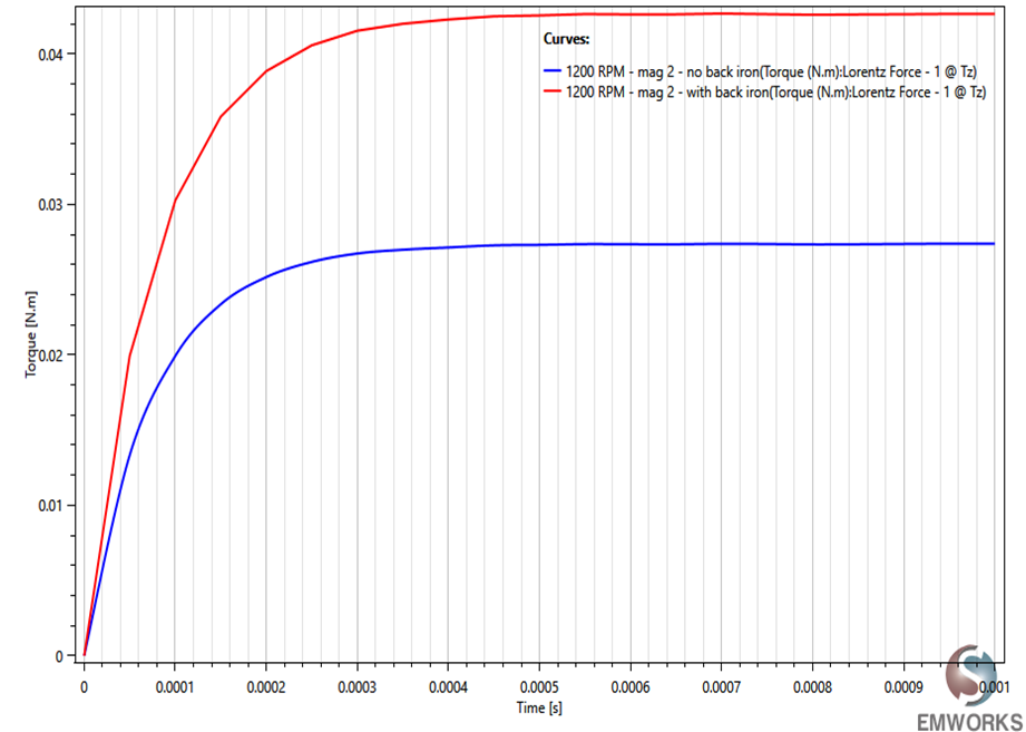
Torque Vs Time with and without the back iron
Torque vs. Time With and Without the Back Iron
We also investigated the effect of the back iron on the torque, as shown above. Unfortunately, there is a significant decrease in torque when the top and bottom back irons are removed. The presence of the back iron is crucial for maintaining a strong and stable magnetic field, which directly impacts the efficiency of the braking system. Without these components, the magnetic field weakens, leading to reduced eddy current generation and, consequently, lower braking torque. This finding underscores the importance of the back iron in ensuring optimal performance of the braking system.
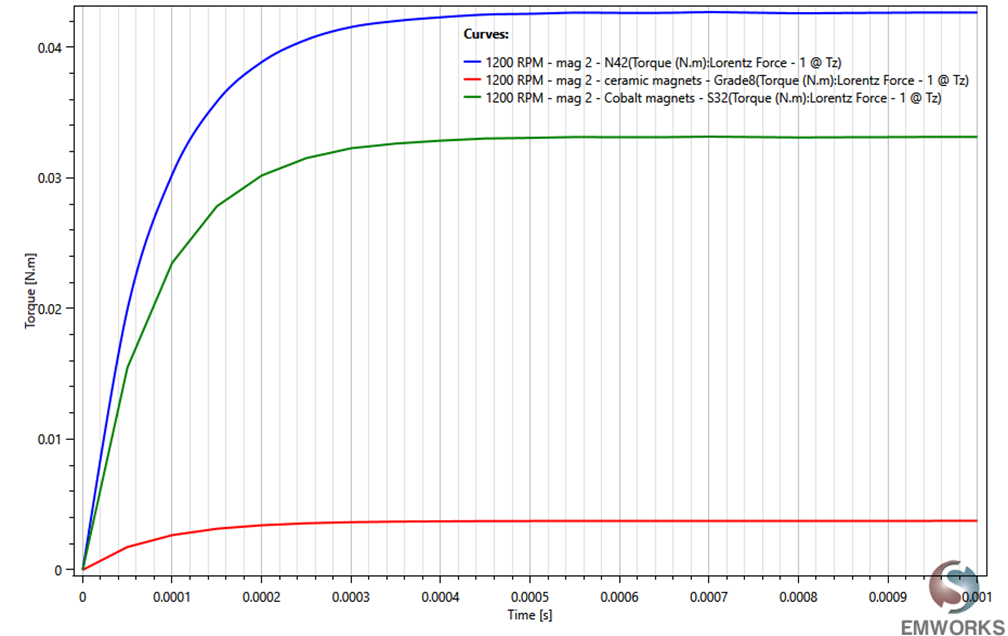
Torque Vs Time for different permanent magnet materials
Torque vs. Time for Different Permanent Magnet Materials
By the same token, we investigated the effect of different permanent magnets, as shown above. As expected, the Neodymium Iron Boron magnet yields the highest torque. Unfortunately, this type of magnet is both expensive and heavy. This trade-off highlights the challenge of balancing performance with cost and weight in the design of our braking system. Despite its superior torque generation, the practical limitations of Neodymium Iron Boron magnets necessitate careful consideration of alternative materials that might offer a more balanced solution.
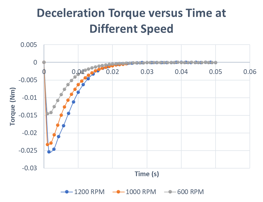
Deceleration Torque Vs Time for 3 different RPM
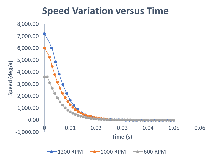
Speed Vs Time for 3 different RPM
Deceleration Torque and Speed vs. Time for 3 Different RPM
After analyzing the steady-state response of the eddy current brake, we examined its dynamic or transient response to better predict the system's real-life behavior. This simulation allows us to compute the braking time and deceleration phase. The deceleration torque plot shows that the torque increases from zero when the brake is activated, reaches a peak, and then decreases until it returns to zero. This decrease in torque occurs as the speed decreases due to the braking force. The interaction concludes when both torque and speed approach zero. The speed plot indicates that, regardless of the initial rotor speed, the rotor comes to a complete halt in approximately 20 milliseconds.
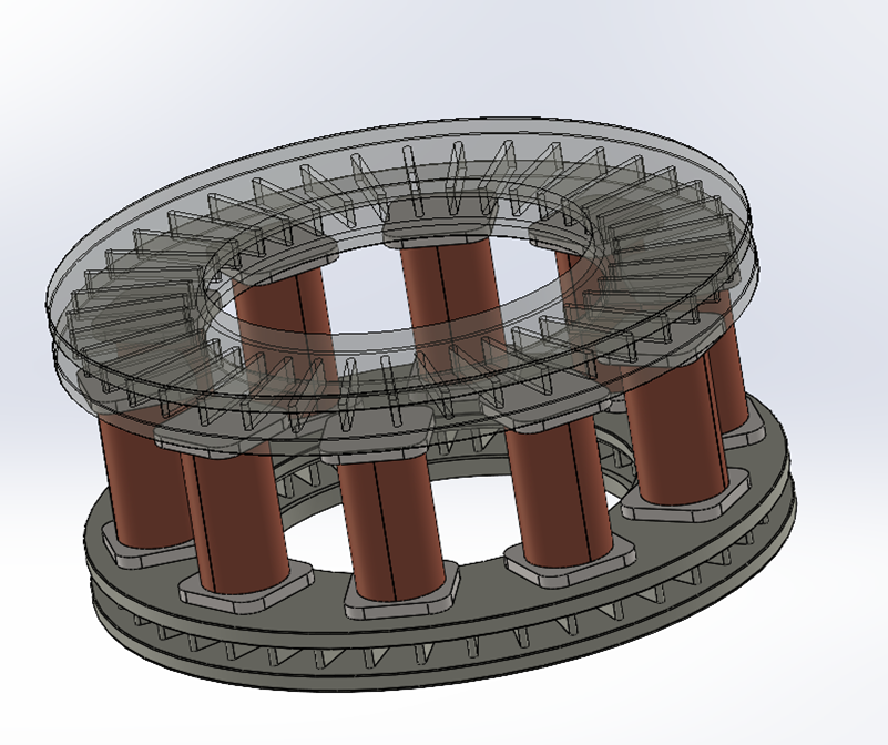
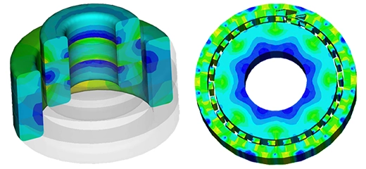
A double-sided ventilated brake
A double-sided ventilated brake
In addition to the axial permanent magnet brake discussed earlier, we also investigated a double-sided ventilated brake, as shown above. In this example, we demonstrate EMWORKS' capabilities to accurately predict the temperature rise caused by the eddy currents generated during motion.
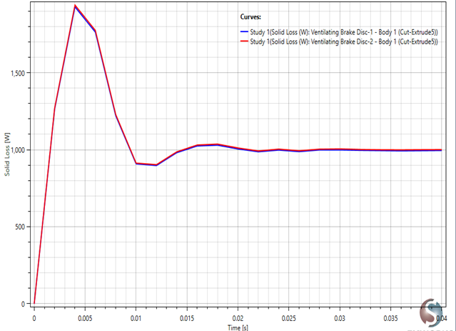
Eddy current loss in the rotating disks
Eddy Current Loss in the Rotating Disks
Eddy current loss in the rotating disks of an eddy current brake significantly impacts system efficiency and performance. When activated, the magnetic field induces eddy currents in the disks, generating heat due to electrical resistance. This heat, known as eddy current loss, causes a temperature rise that can affect the brake's effectiveness and longevity. Managing these losses is crucial to prevent overheating and ensure consistent performance. From the plot above, we can see that the loss in each disk converges to approximately 1000 watts.
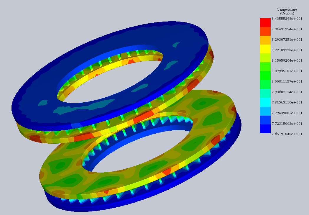
The temperature distribution of a double-sided ventilated eddy current brake
The Temperature Distribution of a Double-Sided Ventilated Brake
The temperature rise in the disks of an eddy current brake due to eddy current losses is crucial for system performance and durability. Induced eddy currents generate heat, raising the disk temperature. Without proper thermal management, this can degrade material properties, reduce braking efficiency, and risk component damage. Effective cooling and optimized materials are essential to dissipate heat and maintain reliability and efficiency. From the plot above, the temperature reaches 84°C in around 90 seconds.
Conclusion
This application note has explored the detailed simulation of eddy current braking systems using EMWORKS software. Through various examples, including axial permanent magnet brakes and double-sided ventilated brakes, we demonstrated the importance of optimizing magnetic field configurations, managing thermal effects, and selecting appropriate materials. Our simulations highlighted the critical factors affecting braking torque, power dissipation, and temperature rise. The results validated by experimental data confirm the accuracy and reliability of EMWORKS as a tool for enhancing the design and performance of eddy current brakes. These insights are essential for developing efficient, durable, and high-performance braking systems in various applications.