Exploring How Frequency Affects Graphite Crucible Induction Heating
Induction heating
Induction heating rapidly generates heat in materials without contact, offering high power density and adjustable penetration. It relies on Lenz's and Joule's laws: a changing magnetic field induces electrical currents, heating the material through energy dissipation. Practically, as shown in Figure 1, induction heating involves placing a conductive component in a magnetic field generated by an inductor coil connected to a power source and capacitor bank. Efficiency depends on factors like inductor placement, component length, power frequency, and skin effect, determining current distribution within the component. Originating in the 1960s, induction heating continues to evolve for various industrial applications.
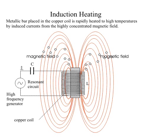
Figure 1 - Induction heating principle
Multiphysics simulation using EMS
Induction heating poses a multifaceted challenge, merging electromagnetism with heat transfer due to materials' temperature-dependent properties. To model these intricacies, we employ Maxwell's equations for electromagnetism and classical heat transfer equations, solved through the finite element method within EMS software.
EMS, or Electromagnetic Simulation Software, facilitates multi-physics simulations by seamlessly coupling electromagnetic and thermal fields. In this scenario, EMS is instrumental in designing and optimizing components like induction coils and graphite crucibles for heating purposes. By conducting AC magnetic simulations coupled with transient thermal analyses, EMS offers a thorough grasp of the system's behavior, crucial for effective design and optimization.
Problem description
Table 1 presents the properties of materials used in our simulation, spanning the induction coil, graphite crucible, and surrounding air. While the Maxwell equations are solved across the entire domain, our heat transfer analysis concentrates on the graphite crucible. We assume the water-cooled induction coil maintains a consistent room temperature throughout. Notably, graphite's electrical conductivity, thermal conductivity, and specific heat demonstrate temperature-dependent traits, depicted in Figures 4, 5, and 6.
| Material | Relative Permeability | Electrical Conductivity | Mass Density (Kg/m^3) |
| Copper | 1 | 5.9980e+7 | 8900 |
| Graphite | 1 | Temperature-dependent | 2500 |

Figure 2 - Curve of electrical conductivity

Figure 3 - Curve of thermal conductivity

Figure 4 - Curve of specific heat
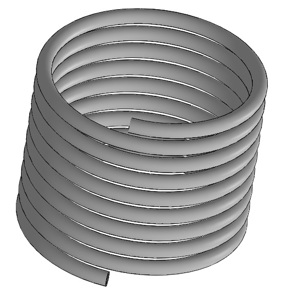
Electromagnetic inputsIn this study, only a solid coil is defined as electromagnetic input as shown in Table 2.
Table 2 - Coil information
| Number of turns | RMS Current | |
| Solid Coil | 9 | 707.21 |
Thermal inputs and initial conditions
Initial and boundary conditions for Heat transfer are listed in Table 2.
| Boundary conditions | Value |
| Initial temperature | 303 K |
| Convection coefficient (h) | 10 (W/m^2*K) |
| Emissivity (Graphite surface) | 0.7 |
Meshing
Meshing is a critical step in design analysis, with EMS employing a method to estimate a global element size for the model, considering factors like volume, surface area, and geometric intricacies. The resulting mesh size, nodes, and elements depend on factors such as geometry, dimensions, specified element size, mesh tolerance, and mesh control.
In the early design stages, when approximate results suffice, a larger element size can speed up the solution process. However, for precision, a smaller element size may be necessary to ensure accuracy and reliability.
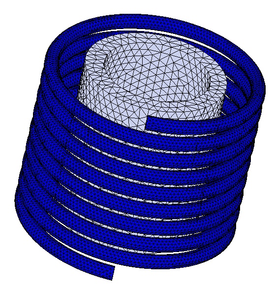
Figure 6 - Meshed model
Results
After completing the AC magnetic simulation and transient thermal analysis, EMS provides electromagnetic and thermal results, including magnetic flux density, field intensity, eddy current distribution, and induced heat power. These datasets are available for visualization and analysis in various 3D formats. Additionally, EMS generates a results table containing critical circuit parameters.
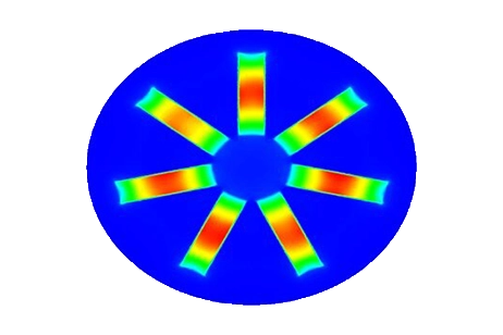
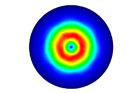
For detailed insights, refer to the figures below. Figures 7, 8, and 10 display magnetic field intensity at frequencies of 1kHz, 5kHz, and 9kHz, respectively. Figure 9 presents a comprehensive depiction of temperature evolution at a specific point on the graphite's surface.
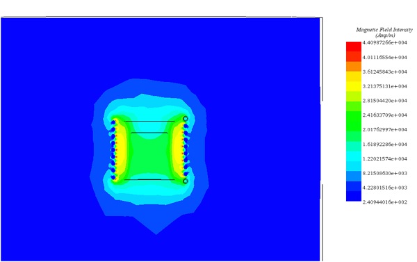
Figure 7 - Magnetic field at t=0s for frequency= 1Khz
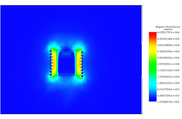
Figure 8 - Magnetic field at t=0s for frequency= 5kHz
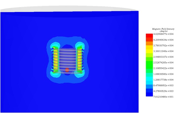
Figure 9 - Magnetic field at t=0s for frequency =9kHz
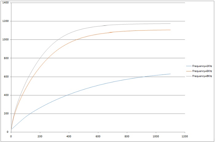
Figure 10 - Temperature evolution at a specific point
Conclusion
The application note delves into the principles and applications of induction heating, a process renowned for its ability to rapidly generate heat in materials without direct contact. Leveraging Lenz's and Joule's laws, induction heating relies on inducing electrical currents in conductive materials within a varying magnetic field, resulting in heat dissipation. Practically, induction heating involves placing a conductive component in a magnetic field generated by an inductor coil, driven by a power source and capacitor bank. This technology, dating back to the 1960s, continues to evolve for diverse industrial applications.
To model and optimize induction heating systems effectively, the application note utilizes EMS software, which seamlessly couples electromagnetic and thermal fields. EMS aids in designing and optimizing components like induction coils and graphite crucibles by conducting AC magnetic simulations and transient thermal analyses. The note provides insights into material properties, boundary conditions, meshing considerations, and simulation results, demonstrating how EMS facilitates a comprehensive understanding of induction heating systems' behavior for efficient design and optimization.
References
B. Patidar, M.M. Hussain,A. Sharma, A.P. Tiwari.August 2016.TRANSIENT NUMERICAL ANALYSIS OF INDUCTION
HEATING OF GRAPHITE CRUCIBLE AT DIFFERENT FREQUENCY. International Journal of Electromagnetics ( IJEL ), Vol 1, No 1,


