Design and Analysis of Wireless Power Transfer Charger for Electric Vehicles
Majdi EL Fahem . Juli 28, 2022
What is Behind the Wireless Power Transfer (WPT)?
In simple terms, wireless power transfer is the transmission of electric power without any direct physical wire or cable connections. The power transfer is usually based on the technology that utilizes electric, magnetic, or electromagnetic fields. WPT happens by creating an alternating magnetic field on the transmitter coil. This magnetic flux is then converted into an electrical current in the receiver coil. The generated electrical current depends on the amount of flux generated by the transmitter coil, and how much of a percentage the receiver coil can capture. The distance, size, and position of the receiver coil relative to the transmitter coil decide the “coupling factor or coupling coefficient” of the two coils.
Ever since the concept of WPT became popular, scientists and engineers begins to develop various techniques to realize this concept. These techniques are mainly classified based on the transmission distance, maximum power, and method used to achieve power transmission. Therefore, WPT can be categorized into the inductive coupling, capacitive coupling, magnetic coupling, and electromagnetic radiation. Moreover, based on the energy encryption and WPT technique, broadly we can divide it into three sections such as near field, medium field, and far field. The comparison among these techniques, their advantages - disadvantages, and applications are tabulated below.
Comparison between Near, Medium, and Far Fields of WPT [1]
Aspect
The Near Field
The Medium Field
The Far Field
The Energy Efficiency
High
High
Low
The Performance of power transfer
High
High
Low
The characteristics of distance, frequency, and number of turns
Easier to transfer power
Easier to transfer power
More complex to transfer power
Advantages and Disadvantages of WPT Techniques [1]
WPT technique
Advantages
Disadvantages
Applications
Inductive Coupling
Simple safe, high efficiency in short range
Short transmission distance, needs accurate alignment
Electric toothbrush and razor battery charging, induction stovetops, and industrial heaters
Capacitive Coupling
Simple structure of couplings, lightweight, low cost, position flexibility, and high frequency
Small power density of the small coupling capacitance
Charging portable devices, power routing in large-scale integrated circuits, Smartcards
Magnetic Resonant Coupling
Long transmission distance, no radiation
Difficult to adjust resonance frequency for multiple devices
Convenient, safe, and effective way to transfer power
Environmentally friendly - Does not harm or injure a human or any living being.
Enhancing the quality of life and reducing the risk of infection and other complications caused by maintenance or replacement of implantable medical devices
What are their Drawbacks?
Low efficiency and higher losses
Expensive
Higher maintenance costs
Not suitable for high power delivery.
Power drastically decreases with misalignment and higher air gap distance.
How Can FEA Simulation Help in Designing an Efficient WPT of an Electric Car?
The graph below shows the main design issues that an engineer needs to tackle while designing and developing a wireless power charging system for electric vehicles. The same graph demonstrates how EMWorks solution can be used to solve these problems. The main key parameter of a WPT system is the coupling coefficient which is affected mainly by the distance and the alignment of transmitter and receiver. It is also impacted by the geometry of these coils. Different scenarios and designs can be investigated to come up with an efficient design iteration that provides higher transmitter energy. Resonant wireless power transfer is a considerably great solution to improve further the efficiency of the charging system.
Through their different magnetic modules, with parametric and multi-configuration features, EMWorks software help to test and solve different iterations and design scenarios. In addition to this, the circuit simulator of EMWorks tools is used to model the power system including different resonant circuit topologies and loads to provide better efficiency and performance of the WPT charger.
Wireless Charger of an Electric Vehicle
Smartphone Wireless Charger
Pacemaker Wireless Charger
Case Study: Different Topologies of a WPT Charger used in Electric Vehicles
Both circular and rectangular coil-based wireless chargers are commonly utilized in electric cars. DD coil, DDQ coil, and bipolar coil are some topologies that are used in wireless charging systems for electric vehicles. These topologies provide certain improvements in terms of coupling coefficients, and they allow more tolerance for misalignment. They can come with ferrite to better direct the magnetic flux and aluminum shielding.
EMS, which is a 3D multi-purpose electromagnetic simulation software, generates plots of the magnetic fields density and current distribution, etc. Different post-processing options including fringe, vector, and lines are overall available through EMWorks FEA software. The plots of the magnetic fields allow us to explore the strength of the magnetic field and its distribution from the transmitter to the receiver and in the air gap region. This can help to optimize the design by maximizing the receiver flux and minimizing the field leakage around the system.
Double D Pad
DDQ Pad
Bipolar Pad
(a)
(b)
Cross Section Plots of the Magnetic Field Results (Single Rectangular Coil): a) Fringe Plot, b) Field Line Plot
Moreover, EMS is used to analyze different topologies of the wireless charger. It helps to predict all the key parameters and solve the design issues of such devices. Investigating the coupling coefficient versus different configurations and the relative position of both transmitter and receiver helps to identify the optimal performance conditions and improve the low-efficiency situations. Through parametric and multi-configuration features, you can iterate more and reach an optimal design with minimum effort and time.
Coupling Coefficients of Different Topologies and Misalignment
Analysis of Different Misalignments: a) Animation of the Magnetic Field vs Different Coil Receiver Positions, b) Coupling Coefficient vs Misalignment Distance
As mentioned above, the EMWorks solution comes with an integrated circuit simulator. It contains several electronic components including resistance, inductor, capacitor, switch, diode, sources, etc. Different resonant inductive coupling topologies can be analyzed to design an efficient wireless device.
Schematic of a Resonant Charger with LCC Compensation Network Circuit Modeled using EMWorks Circuit Simulator
(a)
(b)
Performance of a Wireless Charger for Electric Vehicles: a) Power vs Frequency, b) Efficiency vs Frequency
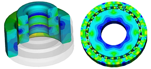
Electromagnetic Losses and Heat Generation
Electromagnetic losses are directly proportional to the frequency. Hence, it is challenging to maintain the loss and the generated heat at low levels since wireless power transfer applications operate at high frequencies. Litz wire is one of the solutions to reduce the eddy loss in the winding. EMWorks software allows to model coils while taking into account the Litz wire parameters of the windings.
In addition to this, AC, DC, and core losses are calculated using EMWorks software to help design more efficient wireless chargers. Finally, you can estimate the temperature of your system using the coupling to the thermal feature. This coupled analysis allows for an accurate and easy Multiphysics simulation.
(a)
(b)
(c)
Loss Density Results: a) Eddy Loss in the Aluminum Shields, b) Iron Loss in the Ferrite Bars, c) Copper Loss in the Windings
(a)
(b)
(c)
Temperature Results: a) Aluminum Shields, b) Ferrite Bars, c) Windings
(a)
(b)
Variation of the Temperature vs Time: a) Animation of the Temperature vs Time, b) Temperature at a Specific Point vs Time
In conclusion, wireless power systems have become integral in various applications, posing unique design challenges. EMWorks offers a comprehensive solution, empowering engineers to enhance wireless power systems and satisfy diverse requirements. Through sophisticated simulations and analyses, EMWorks aids in overcoming obstacles, ensuring efficient and effective wireless charging solutions for electric vehicles and beyond, thereby paving the way for a future of seamless and sustainable power transfer technologies.
By visiting or using this website you agree to the storing of cookies on your device to enhance site navigation,
analyze site usage, and assist in our marketing efforts.
View cookies details.