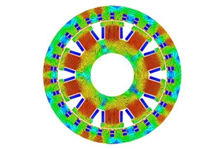
Benefits of Outer Rotor PM Generators for Wind Power
Outer Rotor Permanent Magnet Generators
The use of renewable energy sources, particularly wind power, has gained significant attention in recent years due to its potential to mitigate climate change and reduce dependence on fossil fuels. Within the wind power sector, permanent magnet (PM) generators play a crucial role in converting wind energy into electrical power. Outer rotor permanent magnet (PM) generators have gained attention as a promising technology for wind turbines, offering various benefits over traditional inner rotor designs. However, like any other topologies, outer rotor PM generators also come with their own set of challenges that need to be addressed. In this application note, the performance of an outer rotor permanent magnet generator, with surface-mounted PMs, is assessed using MotorWizard and EMWorks2D software.
Case Study
Using an outer-rotor topology in wind turbine applications offers several notable benefits:
-
Enhanced Power Density: The outer rotor configuration, where the rotor is positioned on the outer side of the stator, allows for a more compact design and higher power density compared to other generator topologies. By utilizing high pole numbers, the generator can achieve the desired power output while maintaining a smaller physical footprint.
-
Increased Torque Generation: High pole numbers in outer-rotor generators enable wind turbines to generate higher torque. This capability is particularly advantageous during low wind speeds, as it facilitates early power generation and improves overall energy capture. Additionally, the ability to maintain efficient operation at higher wind speeds translates into greater power output.
-
Simplified Design and Maintenance: Incorporating high pole numbers in outer-rotor generators can eliminate the need for a gearbox in certain wind turbine configurations. This direct coupling of the generator to the turbine's rotor eliminates the need for speed conversion, resulting in a simplified turbine design. Not only does this reduce maintenance requirements, but it also enhances reliability and potentially decreases the overall system cost.
-
Direct blade connection: The outer rotor topology has made it possible to directly connect the turbine blades with the rotor. This innovation in wind turbine design has opened up new possibilities for increasing efficiency and reducing maintenance costs. By eliminating the need for a gearbox, this configuration simplifies the mechanical components of the turbine, making it more reliable and cost-effective. Additionally, the direct connection between the turbine blades and the rotor also allows for better aerodynamic performance, resulting in higher energy output.
The machine depicted in Figure 1 is a radial flux PMSM generator with an outer rotor configuration. It comprises 24 stator slots and 20 rotor poles positioned on the surface of the rotor. A two-dimensional model of the machine is presented to provide a visual representation.
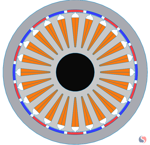
Fig. 1. Geometry of the Machine
The materials used in the machine are shown in Table 1.
| Machine Component | Selected Material |
| Stator and Rotor Laminations | Electrical Steel M800-65A |
| Coils | Copper |
| Permanent Magnets | NdFeB: N4212 |
Table 1. Machine Components and Materials
For this specific application, the outer diameter was restricted to 300 mm and the voltage on the nominal speed must be 380V line to line. To obtain the desired power at the rated speed, and considering size constraints, the area of the coils is designed.
Drawing the machine using MotorWizard tools of EMWORKS
To draw the geometry of the machine, the Motor-Wizard is used. The setting of the MotorWizard is shown in Figures 2, 3, and 4.
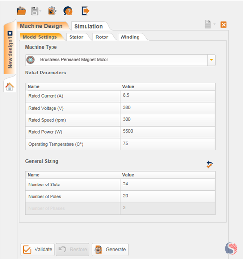
Fig. 2. Model setting in MotorWizard
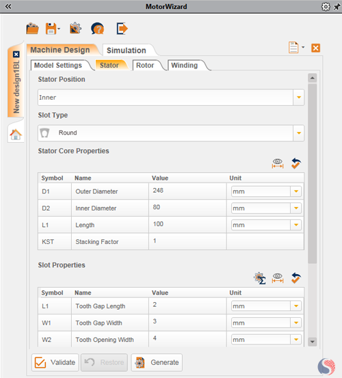
Fig. 3. Stator setting in MotorWizard
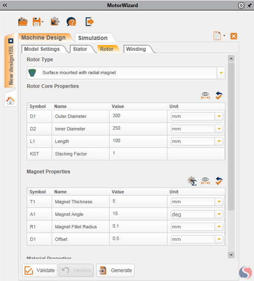
Fig. 4. Rotor Setting in MotorWizard
After generating the model with MotorWizard, the 2D model is ready to set for EMWorks2D software. Two simulations needed to be done to assess the performance of the designed generator. Open circuit simulation to obtain the cogging torque value and a full load simulation to measure the output current and mechanical torque.
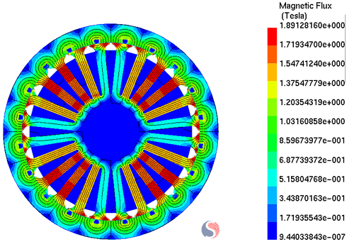
Fig. 5. Flux Density Distribution in the Machine’s Core
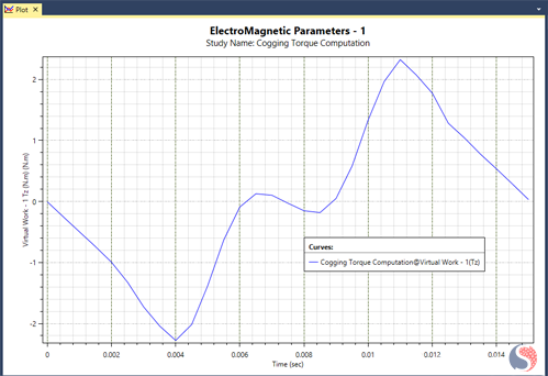
Fig. 6. Cogging Torque of the Final Model Magnet Size
The cogging torque is around 2.2 N.m that is acceptable due to the nominal mechanical torque around 240 N.m in the full load.
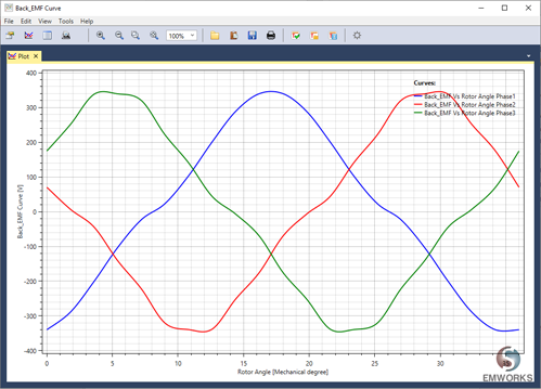
Fig. 7. Back EMF of 3-Phase Windings of the Stator
The peak value of the phase voltage is 340V in no-load and 311V in full load. This peak value will have 380V RMS on the line-line voltages.
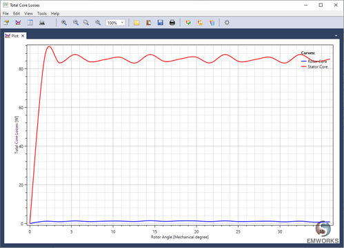
Fig. 8. Core Loss Comparison in the Rotor and Stator of the Machine
Conclusion
In conclusion, the use of 15-degree arc magnets in the generator resulted in a significant reduction of cogging torque in comparison with full-pitch magnets. This reduction in cogging torque is beneficial as it allows for smoother operation and lower mechanical noise and vibration. Additionally, despite the decrease in magnet size, the load output from the generator was found to be acceptable due to lower core loss by reducing the saturated area in the stator teeth. Finally, the simulation of different winding turns led us to the optimum winding to gain the nominal 380V line voltage at the full load operation point.
References
[1] Abdoos, A., Moazzen, M., & Hosseini, S. (2021). Optimal Design of an Exterior-Rotor Permanent Magnet Generator for Wind Power Applications . Journal of Operation and Automation in Power Engineering, 9(3), 193-202. doi: 10.22098/joape.2021.7337.1532
[2] Mamur, Hayati & Sahin, Cihan & Karacor, Mevlut & Bhuiyan, Mohammad. (2020). Design and fabrication of an outer rotor permanent magnet synchronous generator with fractional winding for micro-wind turbines. IET Electric Power Applications. 14. 2273-2282. 10.1049/iet-epa.2020.0318.


