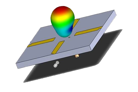
Optimizing UAV Communication: The Role of Advanced Antenna Design
Unmanned Aerial Vehicles
Drones, utilized across military, public services, and commercial sectors, revolutionize tasks from surveillance to delivery. Their operation hinges on reliable antenna-based communication to prevent loss and ensure mission success. Yet, challenges like signal instability, drag, and interference significantly impact their effectiveness.
HFWorks Modeling of Drone Antenna
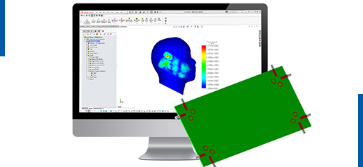
To enhance drone communication reliability, we utilized HFWorks, an electromagnetic virtual prototyping software, to design an antenna based on specifications from a journal article. This design aims to mitigate circuit interference, reduce drag, and minimize the impact of the drone's frame on performance.
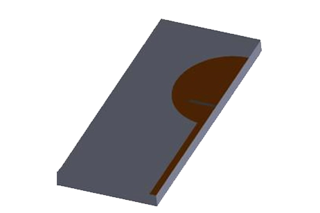
Y-Rounded Shape Antenna with a Convex Bending
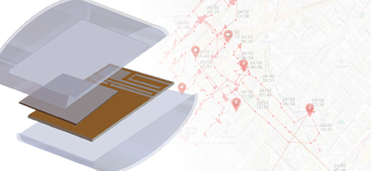
The proposed antenna is low-profile and has a convex curvature which is convenient to minimize the drag problem during the operation of the drone.
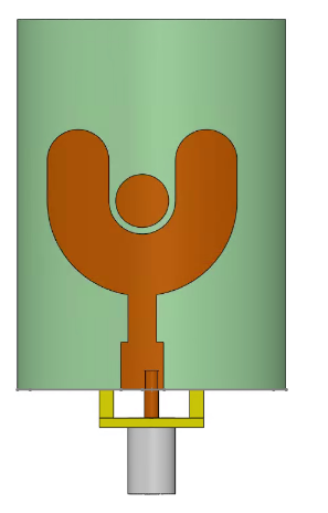
Fig. 1. Top View
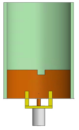
Fig. 2. Bottom View
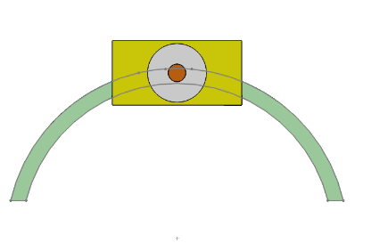
Fig. 3. Front View
The above antenna is simulated, and the following results are obtained:
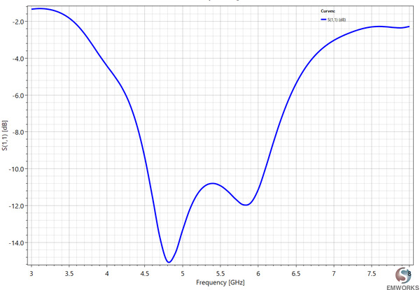
Fig. 4. Return Loss of the Antenna
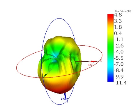
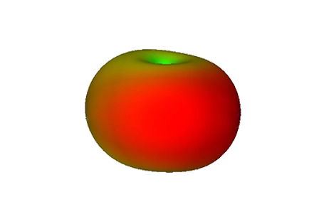
Fig. 5. 3D Radiation Pattern
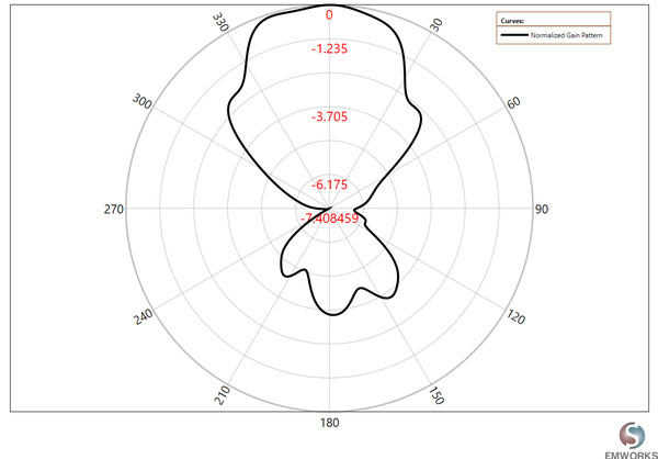
Fig. 6. 2D Radiation Pattern( ?=0° )
| Parameter | Value (Linear) | Value (Logarithmic) | Angle (Theta, Phi) Degrees |
| Incident Power | 1 W | 30 dBm | N/A |
| Accepted Power | 0.936253 W | 29.7139 dBm | N/A |
| Radiated Power | 0.924886 W | 29.6609 dBm | N/A |
| Max U (Theta,Phi) | 0.206269 W/Sr | N/A | ( 344 , 275 ) |
| Max Directivity | 2.80257 | 4.47557 dB | ( 344 , 275 ) |
| Max Gain | 2.59206 | 4.13645 dB | ( 344 , 275 ) |
| Max Delivered Gain | 2.76855 | 4.42252 dB | ( 344 , 275 ) |
| Mismatch Efficiency | 0.936253 | -0.286069 dB | N/A |
| Radiation Efficiency | 0.987859 | -0.0530509 dB | N/A |
| Total Efficiency | 0.924886 | -0.33912 dB | N/A |
| Effective Angle | 4.48387 deg | N/A | N/A |
| Return Loss | Mag(dB) / Phase(deg) | Mag(Linear) / Phase(deg) | Real / Imaginary |
| S(1,1) | -11.955 / -100.729 | 0.252 / -100.729 | -0.047 / -0.248 |
Table 1. Antennas Far-Field Parameters (5.8GHz)
The antenna designed for drone use demonstrated a reflection coefficient of -12 dB at 5.8 GHz, with maximum radiation directed toward the ground. This characteristic makes it particularly well-suited for applications requiring ground-focused communication, such as 3D mapping and aerial photography.
Antenna on Drone
The performance of drone antennas is influenced by their proximity to the drone's body, due to reflections from metals and dielectric loading. Optimal antenna placement is crucial to minimize interference—positioning it at the center risks circuitry noise while mounting it in the middle of the wings offers reduced interference. The drone frame's construction with plastic and the motors' composition of steel and copper also affect antenna function.
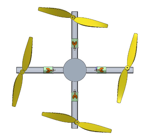
Fig. 7. Antennas on Drone
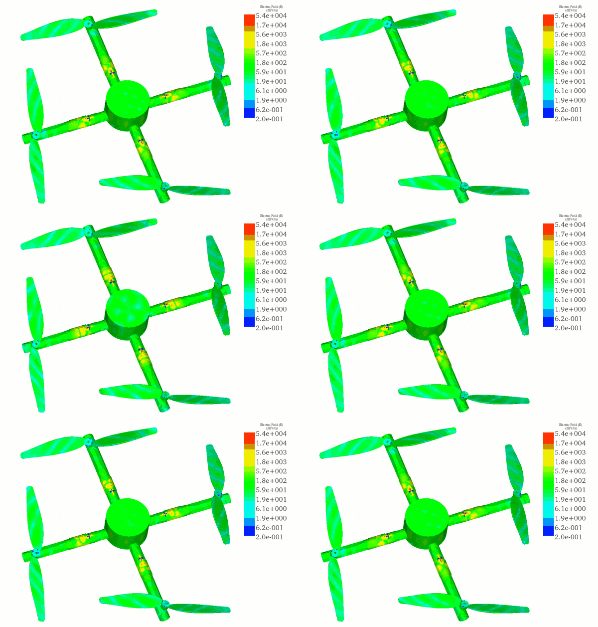
Fig. 8. Electric Field Animation (5.8 GHz)
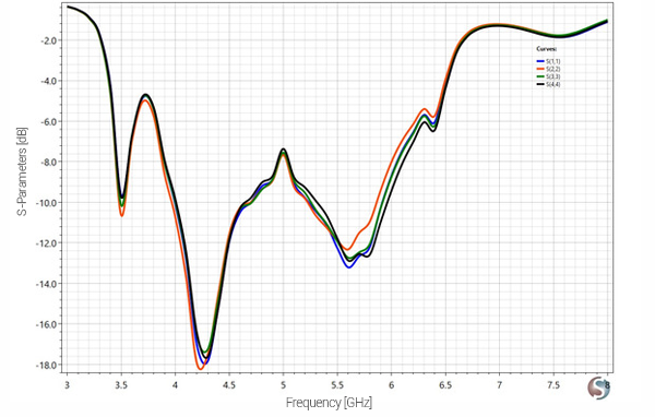
Fig. 9. Return Loss
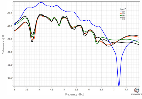
Fig. 10. Coupling Coefficients
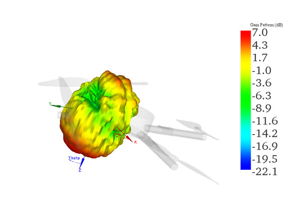
Fig. 11. 3D Radiation Pattern
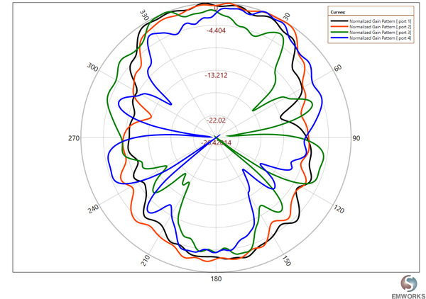
Fig. 12. 2D Radiation Pattern ( ?=0° )
The drone antennas, designed for maximum ground gain, show minor radiation distortion due to the slight permittivity difference between the substrate material and the drone's plastic body. Although the motors, made from metals, are positioned away from the antennas, their impact is minimal, with coupling coefficients below -30 dB at 5.8 GHz, indicating strong isolation between antennas. Installing an antenna on each drone arm enhances the system's spatial diversity, improving overall performance..
Conclusion
FPV antennas play a crucial role in the quality of the transmitted video signal. Low-profile and conformal antennas are indispensable for the successful operation of the drone mission. Placing the antenna on a drone is quite challenging for antenna engineers as there are many parameters to account for. Using a plastic material for the frame of the drone results in less distortion of the transmitted signal. Mounting the antenna in the middle of the wings helps reduce interference with the circuitry of the drone while providing a reliable video signal. HFWorks has been instrumental in addressing antenna challenges and improving drone performance.
References
[1]- L.L. Balderas1, A. Reyna, M.A. Panduro, C. del Rio, and A.R. Gutierrez, 2019, “Low-Profile Conformal UWB Antenna for UAV Applications”


