High-Frequency Heating in Injection Molding
Induction Heating
In injection molding, electromagnetic surface induction heating offers rapid, selective heating, reducing cooling times. This study investigates the impact of heated target thickness and coil position on mold temperature control, using EMS software for electro-thermal simulations of High-Frequency Proximity Heating.
What is high-frequency proximity heating?
High-frequency proximity heating rapidly heats injection molds by inducing a high-frequency current flow on the inner surfaces of closely spaced mold plates (cavity and core). This is achieved through the proximity effect, creating a high-frequency electric circuit. The schematic below illustrates this process.
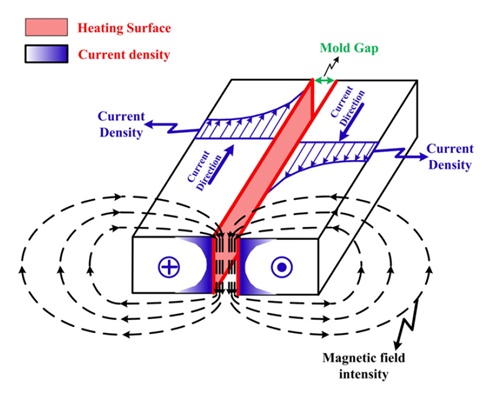
Figure 1 - Schematic illustration of the High-frequency proximity heating principle [1].
CAD Model
The model comprises two parallel square mold inserts with three circular cross-section channels housing the current conductors. Figure 2 displays the chosen inductor design for the simulation, featuring six copper tubes internally hollowed for cooling. Detailed dimensions for each component are listed in Table 1.
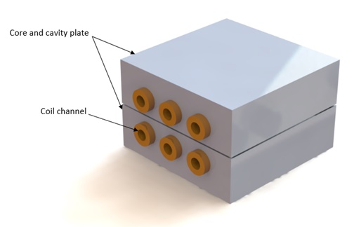
Figure 2 - 3D CAD design of the studied model.
Table 1 - Components` dimensions
| Component | Part | Dimensions (mm) |
| Mold plates | Length | 100 |
| width | 100 | |
| thickness | 32 | |
| Mold gap | 1 | |
| Channel | Diameter | 16 |
| Channel depth | 4 | |
| Distance between channels | 25 | |
| Coil | Outer diameter | 16 |
| Inner diameter | 8 |
Simulation Setup
The primary objective of this analysis is to calculate the temperature distribution across each mold plate surface for improved temperature control during the mold heating process. To accomplish this, the AC magnetic module of EMS is coupled with a transient thermal study to model the induced heating treatment. The simulation setup involves four essential steps.
1. Select the appropriate materials
The mold plates are constructed from Stainless Steel N700, with corresponding thermal and magnetic properties outlined in Table 2.
| Part | Material | Density ( |
Magnetic permeability | Electrical resistivity ( |
Thermal conductivity (W/m. K) |
Specific heat capacity (J/Kg. K) |
| Coil | Copper (Cu) | 8940 | 0.99 | 1.71 E-07 | 400 | 392 |
| Mold plates | Stainless steelN700 (ASTM-A564) |
7900 | 200 | 7.1 E-07 | 16 | 470 |
2. Electromagnetic Input
The inductor coils are characterized as solid coils, capable of sustaining a maximum current of 600 A RMS at a frequency of 70 kHz.
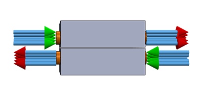
3. Thermal Inputs
The mold plates are initially pre-heated to 40°C, while thermal convection is applied to the surrounding air at an ambient temperature of 25°C, with a coefficient set to 10 W/m²C.
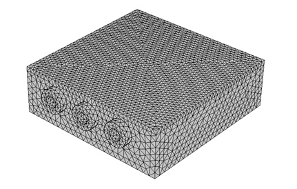
4. Meshing
A fine mesh control was applied to the mold surfaces exposed to the proximity heating effect, as eddy currents primarily concentrate in these regions..
Results
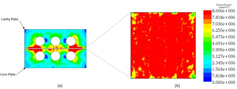
After 15 seconds of induction heating, the simulation unveiled results depicted in the figures below.
The induced current density is highlighted in Figure 5, peaking across the heated surfaces (Figure 5b) between the core and cavity mold plate, aligning well with Reference [1].
EMS facilitates the computation and visualization of temperature distribution on the induced surfaces, showcasing a well-balanced distribution with an average ranging between 80°C and 90°C.
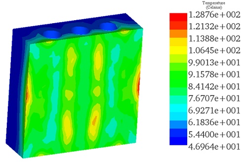
A comparison between the obtained temperature results and those from reference [1] (both experimental and simulation) at the mold surface center demonstrates a strong agreement, confirming the validity of the experimental findings.
| Results | Experiment-Ref [1] | Simulation-Ref [1] | EMS |
| Temperature at cavity plate center (°C) | 83 | 83.4 | 83 |
Figure 7 depicts a secondary comparison between the experimental [1] and EMS simulation results, specifically analyzing the temperature variation at the center of the cavity surface plate over time.
![Temperature variation versus time for both Experimental [1] and EMS results](/ckfinder/userfiles/images/Temperature-variation-versus-time-for-both-Experimental-%5B1%5D-and-EMS-results.jpg)
Conclusion
In this application note, the efficacy of high-frequency proximity heating in injection molding processes is thoroughly explored. By utilizing electro-thermal simulations, the study investigates how variations in heated target thickness and coil position influence mold temperature control. The results demonstrate that high-frequency proximity heating offers rapid and selective heating of mold plates, leading to reduced cooling times and enhanced temperature uniformity. Specifically, induced current density across heated surfaces and temperature distribution reveal well-balanced heating patterns, with average temperatures ranging between 80°C and 90°C. Moreover, comparisons with experimental and simulated data from prior studies confirm the accuracy and reliability of the electro-thermal simulations. These findings underscore the potential of high-frequency proximity heating to revolutionize injection molding processes, improving production efficiency and product quality. By facilitating precise temperature control and minimizing energy consumption, this technology holds promise for various industrial applications requiring intricate molding and rapid prototyping. Overall, this application note highlights the significant advancements and benefits that high-frequency proximity heating brings to the realm of injection molding and manufacturing processes.
References
[1]- Chen, Shia-Chung, et al. "Mold temperature control using high-frequency proximity effect induced heating." International Communications in Heat and Mass Transfer 39.2 (2012): 216-223.


